Camera Calibration
Many applications require knowing the precise pose of a camera with respect to the robot for performing perception tasks. For a camera on the arm that is its pose relative to the end effector, and for a camera fixed in the workspace its pose relative to the robot base. Using a calibration procedure ensures repeatable accuracy of the camera pose without manual measuring and positioning. The calibration Objectives move the robot through a set of waypoints, detect a printed ChArUco board from each one, and solve for the camera pose that agrees with all of those views.
Three Objectives cover the common setups:
Calibrate Eye In Hand Camerafor a camera on the arm looking at a board fixed in the workspace.Calibrate Eye To Hand Camerafor a camera fixed in the workspace looking at a board mounted on the arm.Calibrate Multiple Camerasfor any mix of the two. It calibrates them in one run, then refines them together.
Each one writes the calibrated camera pose and the board pose to its output ports, draws both in the 3D Visualizer, and reports how well the views agree. Steps 5 and 6 cover applying the result to your robot and checking the alignment in the camera pane. Step 7 calibrates the camera's intrinsics.
This how-to guide will walk through the calibration Objectives in the hand_eye_calibration_sim config. It has a UR5e on a linear rail with a wrist camera. The wrist camera looks at a board on a stand in front of the arm. Two fixed scene cameras look at a second board on the wrist. Every camera and board pose in the simulation is known exactly, so you can check the results against the true poses.
Launch the Runtime and Desktop App
We assume you have already installed MoveIt Pro to the default install location. Start the MoveIt Pro Runtime using:
moveit_pro run -c hand_eye_calibration_sim
Then launch or connect the separately distributed MoveIt Pro Desktop App. The Runtime does not serve a bundled user interface.
What You Need
- A printed ChArUco board on a flat, rigid backing. See step 1.
- The camera's image and camera info topics. The pose calibration uses the intrinsics in the camera info as they are. To solve the intrinsics themselves, see step 7.
- The end effector frame of your robot. This is the frame that moves with the camera or with the board. For a camera on the arm, the waypoint generator expects the camera to look along that frame's z axis.
You do not need the pose of the board, and there is nothing to measure or enter. The Objectives estimate the board pose along with the camera pose and write it to the calibrated_board_pose output port. That pose is in the robot base frame for a camera on the arm, and in the end effector frame for a camera fixed in the workspace.
1. Print and Mount the Board
Download a board and print it at 100% scale, with any scaling or fit-to-page option turned off. Both boards below have a 100 mm bar under the pattern. Measure it after printing. If it is not 100 mm, the print came out at the wrong scale and the squares do not match square_length. Print it again at 100% scale. They are sized for the simulation and for a camera at a similar working distance. Other setups need a different size. Any ChArUco board with at least 3 squares on each side and a dictionary that holds enough markers for it works, once you set it in the board port. The editor flags a board that does not qualify, and the two files below are the pages it produces for these presets.
- World board: 7 x 5 squares of 50 mm with 37.143 mm markers, dictionary
DICT_4X4_50. The page is 354 x 262 mm. A3 holds it at a browser's default margins. US Tabloid is about 3 mm short of it, so set the print margins to minimum there. The default board ofCalibrate Eye In Hand Cameraand the world board ofCalibrate Multiple Cameras. In the simulation it stands in front of the arm. In the board editor it is theWorld boardpreset. - Arm board: 5 x 4 squares of 45 mm with 33 mm markers, dictionary
DICT_5X5_50. The page is 236 x 192 mm. US Letter holds it at a browser's default margins. A4 is about 2 mm short of it, so set the print margins to minimum there. The default board ofCalibrate Eye To Hand Cameraand the arm board ofCalibrate Multiple Cameras. Small enough to mount on a wrist, which is where it sits in the simulation. In the board editor it is theArm boardpreset.
Glue the print flat on something that does not bend. Every square must stay square.
The calibration solves the board's pose, so you can place it by eye. Where it goes depends on the camera:
- Camera on the arm. Fix the board in the workspace where the camera sees it from the robot's working poses. It must not move during the run.
- Camera fixed in the workspace. Mount the board on the arm, rigidly.
The board should ideally fit in the image at every waypoint. Its squares must still be large in the image at the working distance, so pick a bigger board for a camera that is far away. If two boards are on the same rig, give them different marker families, as the simulation does. A camera that sees the wrong board mixes two board poses into one solve.
Every calibration Objective takes the board as one board port. Click the edit icon next to it to open the board editor. Pick one of the two presets, or enter the number of squares along each side, the square and marker side lengths in meters, and the ArUco marker family. The editor moves to a larger dictionary of that family when the board outgrows the current one, and keeps one that already fits, since the sizes within a family print the same markers. The editor draws the board as you change it. Download for Printing saves any board you enter as an SVG page that prints at 100% scale, with the 100 mm bar and a caption that repeats the values. Calibrate Multiple Cameras takes a world_board and an arm_board. Read the caption to tell the two prints apart.
2. Create Calibration Waypoints
Calibration waypoints are the robot poses the Objective moves through during calibration. At each one it records an image of the board and the pose of the end effector. The solver uses those pairs to find where the camera is. The calibration Objectives visit every saved waypoint whose name starts with waypoint_prefix (calibration by default). You can save those waypoints by hand in the Desktop App, or let Generate Calibration Waypoints do it.
Move the arm to a pose where the camera sees the whole board near the middle of the image. In the simulation, run Move to Home. Then run Generate Calibration Waypoints. It tilts that pose around a pivot in view_count directions, shifts each tilted pose by up to max_translation so the board moves around the image and changes size between waypoints, moves the arm to each pose it can reach, and saves it as calibration_01, calibration_02, and so on. Run it again and it replaces the waypoints with the same names. Waypoints with higher numbers from an earlier run stay. Delete those in the Desktop App before you calibrate.
The default values are set for the simulation. For your robot, set pivot_distance to roughly the distance to the board. It does not need to be exact:
- Camera on the arm: the distance from the end effector to the board, so every view keeps the board in view.
- Board on the arm:
0, so the board turns in place in front of the fixed camera.
max_translation is how far each waypoint shifts from its tilted pose, in meters. Keep it well below pivot_distance for a camera on the arm. Use 0 to keep the board centered.
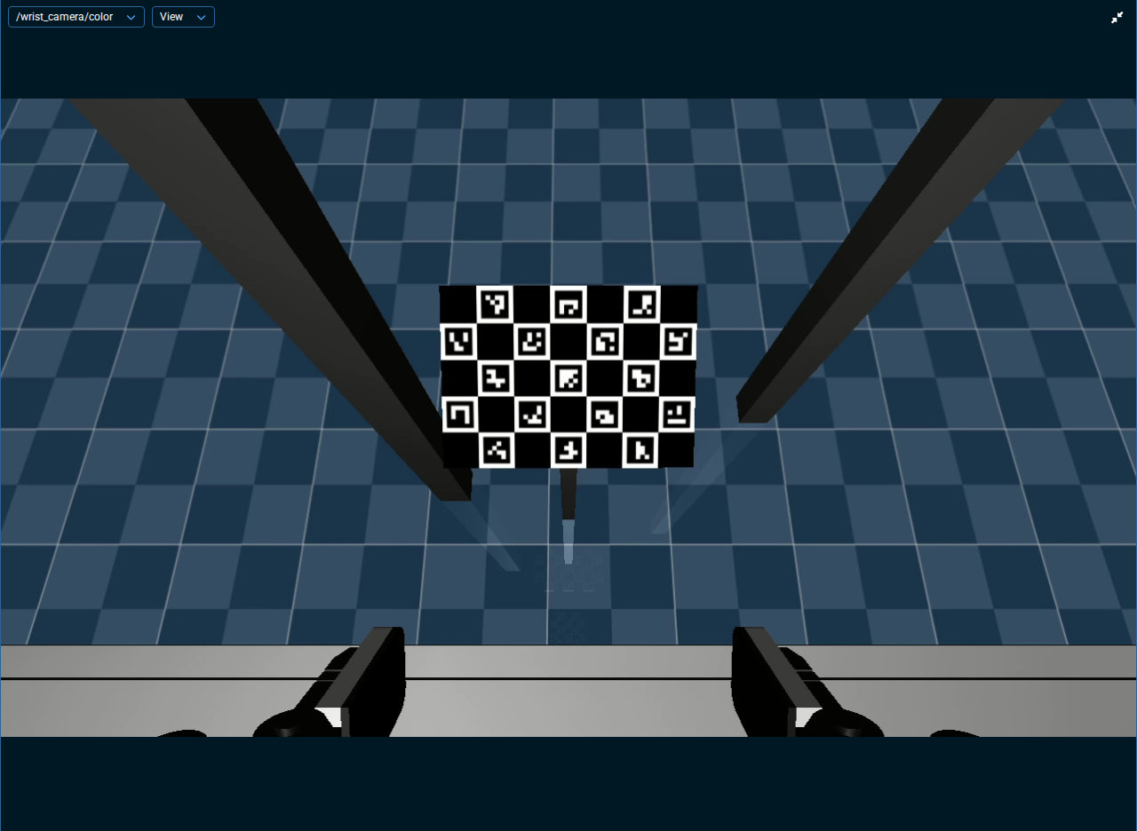
If you save waypoints by hand, change the orientation from one waypoint to the next, not just the position. The solver needs views that rotate the end effector about more than one axis. That turns the camera for a camera on the arm, and the board for a fixed camera. Views that only slide sideways cannot be solved, and the Objective fails instead of returning a poor calibration.
3. Run the Calibration Objective
Camera on the arm. Run Calibrate Eye In Hand Camera. Its defaults match the simulation's wrist camera and the default board. The robot visits each waypoint, waits settle_seconds for the arm to come to rest, captures an image, and records the board corners it finds, along with the end effector pose. After the last waypoint it solves the calibration and draws the camera and board frames in the 3D Visualizer.
Camera fixed in the workspace. Run Calibrate Eye To Hand Camera. Its defaults point at the simulation's narrow scene camera and the arm board.
Several cameras. Run Calibrate Multiple Cameras. At each waypoint, one pass captures an image from every camera. The Objective solves each camera on its own, then a bundle adjustment refines all of them together, so cameras that share a board improve each other's result. The Objective is written for the simulation's rig: one camera on the arm and two fixed cameras. To adapt it to yours, add or remove one camera's set of Behaviors: its GetCameraInfo, its Capture Calibration Sample Subtree inside the waypoint loop, its Solve Behavior, the Behaviors that read and draw its refined pose, and its name in the Script node that lists the cameras for the refinement.
Not every waypoint needs a good view of the board. Each Objective uses the views where it finds the board and lists the waypoints it could not use in the summary.
For your own robot, set the image, camera info, and point cloud topics, joint_group_name, end_effector_frame, base_frame, and the board port. In Calibrate Multiple Cameras, the topics and the camera name are per camera, with prefixes such as eye_in_hand_, and the boards are world_board and arm_board. The frames and the joint group are shared. camera_name ties each recorded sample to its solve and labels the result, so give every camera its own name. For a fixed camera, set base_frame to a frame that does not move relative to the camera, such as world.
4. Interpret the Calibration Results
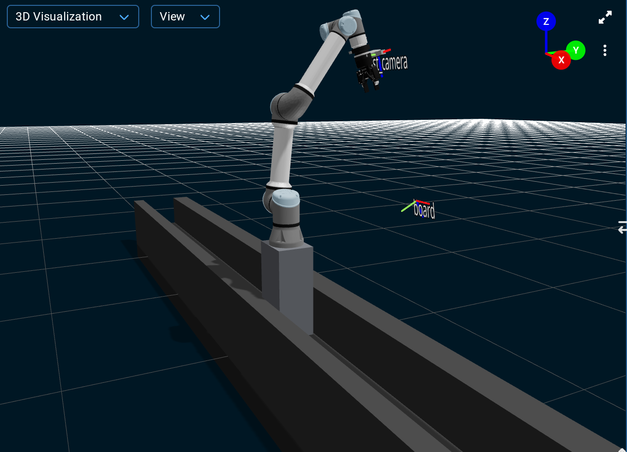
The camera frame and the board frame appear in the 3D Visualizer. The labels are the camera name and board, or world board and arm board in Calibrate Multiple Cameras. The same poses are on the calibrated_camera_pose and calibrated_board_pose output ports, so another Behavior can use them. Calibrate Multiple Cameras prefixes those ports per camera. Each Objective also takes a point cloud snapshot from the camera after the solve and draws it in the 3D Visualizer, so you can check the calibration against the robot model.
The solve reports one line per camera in the Alert Sidebar:
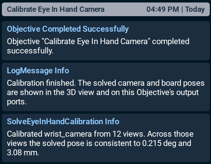
The solver finds the one camera pose that fits all the views best. The two numbers say how much the views disagree with that pose. Small numbers mean the views agree with each other. When they do not, the Objective warns:
The calibration of wrist_camera is inconsistent across views: 75.359 deg and 161.74 mm, limits 5.730 deg and 50.00 mm. Check the board dimensions, the end effector frame, whether this Behavior matches the camera's mounting, and that the robot is stationary at each view.
The run still succeeds, so you can look at the markers, but do not use the result. The limits in the warning come from the rotation_residual_warn and translation_residual_warn ports of SolveEyeInHandCalibration and SolveEyeToHandCalibration. The Objectives do not expose those ports. To change them, edit the Solve Behavior in a copy of the Objective.
The summary lists the waypoints the Objective could not use, for example:
Calibrated scene_camera_narrow from 7 of 12 views. Across those views the solved pose is consistent to 0.054 deg and 1.44 mm. No usable board pose from waypoints calibration_07, calibration_08, calibration_09, calibration_10, calibration_11.
Dropped views are normal in the simulation: the waypoints are generated for the wrist camera, and the same set serves the scene cameras, which see the board from elsewhere. How many drop depends on the waypoints and on where each camera sits. You can adjust the waypoints so that every camera sees the board at every one, but the solve only needs 5 usable views and fails below that. More views, with more variation in orientation and position, give a better result.
Calibrate Multiple Cameras adds a line for the refinement, for example:
Refined all 3 camera poses together. The board corners now line up with the images to within 0.098 px on average, down from 2.220 px.
This number is the distance, in pixels, between where each board corner was seen and where the calibration predicts it. A fraction of a pixel is a good fit. The Objective warns when the fit stays above rms_reprojection_warn_px (1.0 px by default) or when the refinement stopped before converging. The refined poses still replace the solved ones in that case, so read the warning before you use them. If the refinement fails outright, the Objective keeps the per-camera results from the solve.
The simulation publishes the true pose of every camera and board on TF, as wrist_camera_optical_frame, scene_camera_narrow_optical_frame, scene_camera_wide_optical_frame, world_board_top, and arm_board_top, so you can compare. A good result in this scene lands within a millimeter or so of the true pose, and the refinement brings it closer. A result that is centimeters out points at the board dimensions or the camera mounting, not at the solve.
5. Apply the Result to Your Robot
The calibrated camera pose is the pose of the camera's optical frame, with z pointing out of the lens. For a camera on the arm it is given in the end effector frame. For a fixed camera it is given in the base frame. It is on the Objective's output port and drawn in the 3D Visualizer. How you apply it depends on how your robot description models the camera:
- Publish a static transform. Leave the camera out of the robot description and publish the calibrated pose from your launch file with a static transform publisher. Its parent is the frame the pose is given in and its child is the camera's optical frame. There is nothing to convert. Do not publish it from a Behavior that runs once. That breaks later transform lookups.
- Edit the URDF. If the camera's fixed joint has the optical frame as its child, replace the joint's origin with the calibrated pose, expressed in the joint's parent link. A robot description usually places a camera differently: a fixed joint attaches the camera model's mount link to the robot, and the optical frame sits at a fixed offset from that link, set by the camera model. To update that joint, turn the optical frame pose into the pose of the mount link in the joint's parent link. Express the mount link's current pose and the calibrated pose in the optical frame, with
CreatePoseStampedandTransformPoseFrame. Then apply the calibrated pose to the mount pose withTransformPoseWithPoseand express the result in the joint's parent link. - Build the joint with xacro. Keep the calibrated values as xacro properties or arguments and write the joint's origin from them. The conversion is the same as for the URDF edit.
To get the numbers out of the Objective, add SavePoseForUrdf after the calibration Subtree in an Objective of your own. It writes the pose as a URDF origin line, <origin xyz="..." rpy="..." />, to a file in the objectives folder of your robot configuration package. Set its calibration_pose_stamped port to the pose, in the frame you want the origin in, and file_name to the file. Note that you need to restart the Runtime for a change to the description or the launch file to take effect. If you rerun the calibration after that, the new result should be close to the pose you applied.
6. Check the Alignment in the Camera Pane
After you apply the calibrated camera pose and restart the Runtime, compare the camera image with the robot model, the planning scene, markers, and point clouds in the camera pane of the Desktop App:
- Open the camera's rectified image and enable View → Show 3D Overlay. In the simulation this is
/wrist_camera/color, which has no distortion. - Set 3D Overlay Camera Info Topic to the
sensor_msgs/msg/CameraInfotopic of that image. The overlay projects the 3D scene into the image with those intrinsics and the transform of the optical frame. - Adjust Image Opacity to compare the robot and scene edges with the image. At 100% only the image shows. Use the display controls of the 3D Visualizer to choose which elements appear.
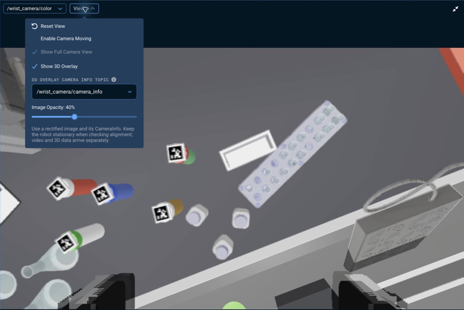
The screenshot uses the lab_sim robot configuration package. The same controls apply to the cameras in this guide. The overlay draws the camera pose that TF publishes now. It does not read the Objective's result, so apply it first.
Keep the robot and the scene still while you look. The video and the 3D data arrive separately. Compare several features across the image. Agreement at one spot does not show that the calibration holds across the workspace. A point cloud from the same camera shares its calibration errors, so compare against robot links and scene objects whose poses do not come from that camera.
The overlay needs a rectified image and its matching camera info. It does not correct the distortion of a raw image, and it does not warn you when you select a raw one. The image drifts from the geometry toward the edges. The calibration Objectives take the raw image, so on your robot the overlay and the Objective use different image topics. The simulated cameras publish no distortion, so one topic serves both. If you move a simulated camera, disable Enable Camera Moving and select Reset View before you check the alignment. See Checking Camera Calibration for the image requirements and the overlay's status messages.
7. Calibrate the Camera Intrinsics
Calibrate Camera Intrinsics solves the focal lengths, the principal point, and the distortion coefficients of a camera from views of the board. It also checks the intrinsics the camera publishes against the same views. The pose calibration uses those published intrinsics as they are, so run this Objective when you are not sure they are right. That includes after you change the lens or the image resolution, and when a pose calibration comes out consistent but wrong.
You can keep the camera still and move the board by hand, or let the arm move through saved waypoints. Set these ports for your camera:
image_topic: the raw image. Do not use a rectified image. Its distortion is already removed, so the solved coefficients would not describe the lens.camera_info_topic: the camera info of that image. The Objective checks these published intrinsics against the calibrated ones.distortion_model:plumb_bob,rational_polynomial, orautofor the model the camera info declares.plumb_bobfits k1, k2, p1, and p2 and holds k3 at 0, because views that stop short of the image corners cannot pin k3 down. Userational_polynomialfor a wide-angle lens that needs more radial terms; it fits 8 coefficients and needs more views. The Objective fits no other models.board,end_effector_frame, andbase_frame, as in step 3.
Move the Board by Hand
The camera stays still and you move the board in front of it. This works for a fixed camera, or for a camera on the arm while the arm stays still. In the simulation the board is fixed on its stand, so use the waypoints below.
- Open the camera's raw image in a camera pane. The Objective's prompts appear in the Alert Sidebar. To see them as toast messages instead, open Alert Settings in the Alert Sidebar, enable Info under Toasts, then close the Alert Sidebar, since toasts stay hidden while it is open.
- Run
Calibrate Camera Intrinsics. Before each sample, one prompt tells you to move the board to a new position, and a second tells you to hold it still until the next prompt. You getmove_secondsto move it andsettle_secondsto hold it, 2 seconds each by default. The Objective takesmanual_sample_countsamples, 20 by default. - Between samples, change the distance of the board and tilt it left, right, up, and down, by up to about 45 degrees. Bring it to the edges and corners of the image as well as the center. The board may run past the image edge when you bring it to a corner. Keep the board sharp, turn off autofocus, and keep the zoom fixed.
Move the Arm Through Waypoints
This works for a camera on the arm. The board stays in place and the arm moves the camera. The Objective moves the arm to each waypoint, waits settle_seconds, and records the board corners it sees.
The distortion is measured only where board corners land, so the views must bring the board close to the camera and move it across the image. To create the waypoints:
- Move the arm so the board fills most of the image, and save the pose as a waypoint named
In Front of the Board. It is the starting pose for this calibration, so you can come back to it whenever you calibrate again. In the simulation the waypoint already exists, so runMove In Front of the Boardinstead. - From that pose, run
Generate Calibration Waypointswithwaypoint_prefixset tointrinsicandpivot_distanceset to0. The arm then tilts the camera about the origin ofend_effector_frameinstead of about a point on the board, which sweeps the board across the image. Keep the other ports at their defaults. - Run
Calibrate Camera Intrinsicswithuse_waypointsset totrueandjoint_group_nameset for your robot. Its defaultwaypoint_prefixisintrinsic, so it visits the waypoints from step 2.
Do not start the name of the starting waypoint with intrinsic. The Objective visits every waypoint whose name starts with its prefix, so it would visit that one too.
Read the Result
The Alert Sidebar shows a summary with the calibrated focal lengths, principal point, and distortion coefficients. Next come the fit error, the uncertainty, and how much of the image the board corners covered. The uncertainty is how far a one standard deviation error in the focal lengths and principal point would move a board corner. The summary then says how far the published intrinsics differ from the calibrated ones, and ends with any views it could not use.
A warning follows the summary when a check fails. It names a fix for each problem. Do not use the result while any of these remain:
- Coverage. The board corners covered too little of the image, so the distortion near the edges is not measured. Add views with the board near the image corners.
- Uncertainty. The calibration is too uncertain to check the published intrinsics against the 2 px limit. Add views at other tilts and distances, and with the board near the image corners.
- Distortion. The calibrated distortion cannot be undone. A pixel sent through it and back does not land where it started, so rectified images and 3D positions computed from pixels would be wrong near the image edges. Add views with the board near the image corners.
- Fit. The views do not agree on one set of intrinsics. Check that the board is flat, that the board and the camera are still during capture, and that the board dimensions match the print. The warning names the view that fits worst. With waypoints, delete that waypoint and run again. By hand, run again with sharp, varied views.
The warning also says when the published intrinsics differ from the calibrated ones by more than the 2 px limit and by more than the calibration's uncertainty explains. When no other check fails, it tells you to use the calibrated values.
Use the Result
The calibrated intrinsics are on the calibrated_camera_info output port as a sensor_msgs/msg/CameraInfo. In an Objective of your own that runs Calibrate Camera Intrinsics as a Subtree, a later Behavior can read them from that port. The Objective does not write them back to the camera. To keep them, copy fx, fy, cx, and cy from the summary into both the camera matrix and the projection matrix of your camera driver's calibration. Copy the distortion coefficients too, and set the distortion model to the one the summary names. Many drivers read this calibration from a camera info YAML file named in their launch file. Restart the Runtime, then run the Objective again to confirm that the published and calibrated intrinsics agree.
Troubleshooting
- No usable board pose from many waypoints. Open the camera's image pane and step through the waypoints. The whole board should be in the image, sharp, and not seen at a grazing angle. Check the
boardport against the print's caption, including the dictionary. - Inconsistent across views. Check the board dimensions. Check that
end_effector_frameis the frame the camera or board really moves with, and that the camera and the board are mounted rigidly. Raisesettle_secondsif the arm is still moving when the image is taken. Check that you ran the Objective for the right mounting. - The solve fails for lack of views or lack of rotation. Add waypoints, or generate them with a larger
tilt_angle_deg. Views must rotate the end effector, not only move it. - Generated waypoints are skipped. The arm cannot reach the pose at any tilt and shift, or the pose collides or leaves the arm's current posture. Leaving the posture means the arm would need an elbow or wrist flip to get there. Clear the space around the arm and the board, move the arm to a pose with more room, or lower
tilt_angle_degormax_translation. - The result is consistent but wrong. The pose calibration uses the intrinsics in the camera info as they are. A wrong focal length or distortion model shifts the result without making the views disagree much. Run
Calibrate Camera Intrinsicsto check them.