Keepout Zones and Saving/Loading Planning Scene
The Keepout Zones feature is designed to quickly define regions in the workspace where the robot(s) is prohibited from entering or interacting. This is crucial for avoiding obstacles and ensuring safe operation in dynamic environments. This guide informs on how to create, manipulate, and manage keepout zones within the planning scene.
Keepout zones are implemented as 3D cubes in the planning scene. This how-to guide will walk through:
- Creating and visualizing keepout zones in the 3D planning scene.
- Manipulating keepout zones, including moving, rotating, and deleting them.
- Naming keepout zones and setting their color and transparency.
- Saving and loading keepout zone configurations to the planning scene.
Creating a Keepout Zone
You can create a keepout zone in the 3D planning scene by defining its size, orientation and position. This keepout zone will prevent the robot from moving into this region.
To create a keepout zone:
- Open the Mode menu in the top left of the MoveIt Pro Desktop App and select Planning Scene Editor.
- Click the + Keep-Out Zone button to create a new keepout zone.
- Adjust the size, position, and orientation parameters of the keepout zone. The parameters are as follows:
- Size: Set the width, height, and length of the keepout zone. Drag the jog strip beside each field, or type the value.
- Position: Set the x, y, and z coordinates to position the keepout zone in the workspace, the same way.
- Orientation: Use roll, pitch, and yaw sliders to rotate the keepout zone around its axes.
Dragging a jog strip raises or lowers its value by how far you drag, not by where you release, so a zone can be made any size and placed at any coordinate — there is no end of travel to reach. Hold Shift while dragging to move ten times finer, or click the strip and use the arrow keys to change the value one step at a time (Shift plus an arrow key for a tenth of a step).
Size stops at 0.01 m, the smallest box the planning scene accepts. The red stretch on a size strip marks the values below it, and slides into view from the left as the zone gets smaller, so the floor is visible on the ruler rather than announced only once you hit it.
Orientation keeps an ordinary slider, because roll, pitch, and yaw span the whole circle and the slider's ends are the real ends of the value.
Manipulating Keepout Zones
Once a keepout zone has been created, you can manipulate it further. It initially appears already selected, with an outline. You can move, rotate, or delete the keepout zone using the interactive marker that appears when the zone is selected. A deselected keepout zone loses the outline and the interactive marker, and both return when you select it again.
Select a zone in the 3D Visualizer to show its name, transparency, color, Clone and Delete buttons, size, position, and rotation in the sidebar.
The Runtime names a new zone keep-out-zone-1, keep-out-zone-2, and so on, one past the highest generated number currently in the planning scene. Deleting the highest-numbered zone makes its number available again; deleting all generated zones restarts numbering at keep-out-zone-1. Connected to a Runtime from an earlier release, the Desktop App gives a new zone a generated UUID instead. Collision and planning error messages, and the Alert Sidebar, name a zone by this ID, so you can tell which zone caused a failure.
- Move: Click and drag the keepout zone to a new position using the arrows on the outside of the interactive marker.
- Rotate: Use the circular interactive marker that appears on the edges of the keepout zone to adjust its rotation. Click and drag the circular handles to rotate the keepout zone around its axes.
- Delete: To remove a keepout zone, select it and press the Delete or Backspace key. Alternatively, click the Delete button in the side panel.
- Clone: To reuse a keepout zone's size, rotation, color, and transparency, select it and click the Clone button in the side panel. The copy appears beside the original with the next
keep-out-zone-<N>name, or a generated UUID on a Runtime from an earlier release, and becomes the selected zone, ready to be dragged into place.
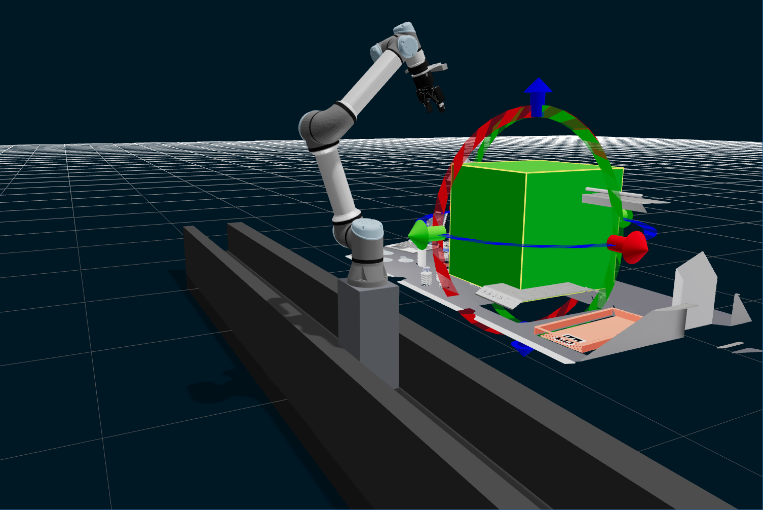
In the Planning Scene Editor, you can select and edit a keepout zone from any of the 3D views. The orthographic views make a misaligned zone easy to spot and correct: click the zone in the X-Axis (Side), Y-Axis (Front), or Z-Axis (Top) pane, then drag the arrows or the ring facing you. The selection and interactive marker appear in every open 3D view, the other views follow the zone as you drag, and the side panel picks up the new pose when you release the handle. To pan an orthographic view, drag with the right mouse button, or hold Shift and drag.
Lock keepout zones, under View in the 3D Visualizer pane, takes selection and the interactive marker away from every keepout zone, so none of them can be clicked or dragged by accident. While the lock is on, a zone cannot be selected or renamed. The appearance controls shown when no zone is selected still work, because color and transparency change only how zones look. Creating or cloning a zone switches the lock off, because the new zone arrives selected and ready to place. While teleoperation is active, creating a zone does not switch the lock off.
Naming Keepout Zones
Select a zone, click its name in the sidebar, and type a new one. The zone's tag in the 3D views follows as you type. Press Enter or click away to rename the zone: the name replaces the zone's ID in the planning scene. To hide the tags, clear Show zone names in 3D views below + Keep-Out Zone. The zone keeps its geometry, pose, and color, and it still blocks motion. Renaming requires a Runtime that provides /rename_keepout_zone; on an earlier Runtime, update the Runtime before renaming zones.
A zone's ID is its name, so:
- A zone whose ID is a UUID, such as one in a scene file saved by an earlier release, shows no tag, and any other ID shows one. Every zone the Runtime names therefore has a tag.
- Anything that refers to the zone by ID, such as an Objective, must use the new name.
- The field shows a message, and the zone keeps its current name, if the new name is empty, contains
/, is<octomap>, or is already used by another object or a robot link. A name that a frame or an allowed-collision entry in the planning scene already uses is refused too, and a message explains why. The Runtime checks the source and the new name, then renames the current object under one scene lock. If another user has already renamed the source or taken the new name, the request is refused without creating a copy. An object attached to the robot cannot be renamed until it is detached. An object with explicit or default collision rules cannot be renamed until those rules are removed, because renaming would drop them. - A zone with allowed-collision rules keeps its name, and an error says why: renaming it would drop those rules, so it would collide where it is now allowed to.
- If the connection fails before a rename is confirmed, the Desktop App keeps the latest scene published by the Runtime, cancels waiting edits, and blocks selection of either affected name and further renames. Reconnect to the Runtime, check the zone's name and pose, then retry the edits.
Setting Color and Transparency
Set one zone's look with the color swatch and transparency slider under its name after selecting it. To see how well a zone covers a point cloud, raise its transparency. Live color and transparency updates need Runtime 10.2 or newer; on an earlier Runtime, a saved color can show its previous value until the next scene update.
When no zone is selected, the sidebar shows global Transparency and Color controls under Defaults for all zones. New zones start with these values; transparency defaults to 10%:
- Changing a global control changes no existing zone. It sets only what the next new zone starts with.
- Objects attached to the robot keep the color that marks them as carried. Apply to All does not change them, and you can still select one to edit its appearance.
- The global values are saved locally by the Desktop App, not in the scene. A zone loaded from a scene file with different values keeps them.
Click Apply to All to set every existing zone to the global values in one step. It changes appearance only, and leaves each zone's name, geometry, and pose as they are. The note beside it counts the zones that differ from the global values, and the button is disabled when every zone already matches.
Transparency stops at 80%, so a zone that blocks motion stays visible. Selecting a zone by clicking it in the 3D Visualizer works at any transparency.
Setting the Link Padding
The Robot link padding field, with the unit m beside the input, under Scene Settings in the Planning Scene Editor sidebar sets one value for the whole robot: the distance, in meters, by which each robot link's collision geometry is inflated for checks that use scene link padding. Checks that leave self-collisions unpadded do not apply this margin between robot links.
- Once valid live scene data arrives, the field shows the scene's current padding, including a value set in the robot configuration at startup. An empty padding list shows
0; setting a value uses the loaded robot's URDF link names. Until valid scene data is available, the field shows Unavailable and cannot be edited. - If the links have different paddings, for example after an Objective padded only some of them, the field is empty and shows Mixed. Setting a value replaces every link's padding with it.
- Drag the ruler or use its arrow keys to adjust the padding; hold Shift for finer changes. Releasing the drag or key applies the final value. You can also type a value, which applies automatically after a 300 ms pause, or press Enter to apply it immediately. The padding must be a finite number of meters,
0or greater; anything else is rejected with a message naming Robot link padding, and the scene is left unchanged. If the update fails, the field keeps your text; press Enter to retry.
Plans that fetch the live planning scene and inherit its padding use the new value without a restart. Previously captured scenes, including scenes held by MTC stages, keep their captured padding. Behaviors whose collision_check_params port overrides the scene's link padding (override_scene_link_padding: true), or whose deprecated link_padding port supplies an override, keep using their own value. This field sets robot link padding only; world-object padding is set elsewhere.
Saving and Loading Keepout Zones
After defining your keepout zones, you can save them to a .scene file on your computer:
- Click the Export Scene button in the Planning Scene Editor sidebar.
- The installed app asks where to save the file. In the web app, the browser saves it like any download; turn on its option to ask where to save each file if you want to pick the folder and name.
Each zone's name, color, and transparency are saved with it.
To load a previously saved planning scene, including keepout zones:
- Click the Load Scene button in the Planning Scene Editor sidebar.
- Choose the
.scenefile in the file dialog.
Scenes saved by earlier versions of MoveIt Pro are in ~/.local/share/moveit_pro/planning_scenes/ on the Runtime computer. Copy one to the computer running the MoveIt Pro Desktop App, then load it with Load Scene.
Loading replaces the objects in the current planning scene with the ones in the file, so export the current scene first if you want to keep it. If the file is not a valid scene file, MoveIt Pro shows an error and leaves the current scene unchanged.
You cannot load a scene while an Objective is running; stop it first. Loading a scene also removes any allowed collisions an Objective set for the replaced objects, because scene files do not store them. Objects the robot is holding keep theirs. A loaded keepout zone applies to motions planned after the load; a trajectory that is already running is not re-checked against it.
Export Scene also saves the scene's link padding. Export rejects world-object names that match a robot link or attached body before creating or overwriting the file; rename the conflicting world object before exporting. Load Scene validates the file before replacing collision objects and applying its padding; a rejected file leaves the current scene unchanged. Replacement removes the previous world objects' pairwise collision exemptions and disables any previous object-specific default exemption. Robot-link and attached-body collision rules are unchanged. Both scene-file load modes reject world-object names that match a robot link or an attached body; rename those objects in the file before loading. Only known links named in the file are updated. Unknown links are skipped, and omitted links keep their current padding, which can produce Mixed when loading a file saved for another robot. Files exported by earlier versions carry no link padding; loading one keeps the current padding. Sensor octomaps and attached bodies are not restored from scene files. Replacement clears the previous world objects' classification and colors, including when a file reuses an object ID. Object classification is not stored in scene files; a loaded object receives only the color the file supplies.