Cartesian Path Following
Tutorial Level: Intermediate
Many applications require moving the arm end-effector along a given path in 3D space. Some examples include welding, sanding, inspection, door opening, etc.
This tutorial will walk through an example Objective that defines a path in 3D space and plans for a robot trajectory that can follow that path.
Launch MoveIt Pro
We assume you have already installed MoveIt Pro to the default install location. Launch the application using:
cd $HOME/moveit_pro
./moveit_pro run -c picknik_ur_mock_hw_config
1. Run the “Move Along Path” Objective
To get an understanding of what path following means in practice, run the Move Along Path Objective.
This Objective makes the robot end-effector follow a rectangular path covering two cells of the scene grid:
2. Objective overview
After running the Objective, open the Behavior Tree to learn how the Objective is defined.
Select the “Objective Builder” tab, click on the Move Along Path Objective, and then select “Edit”.
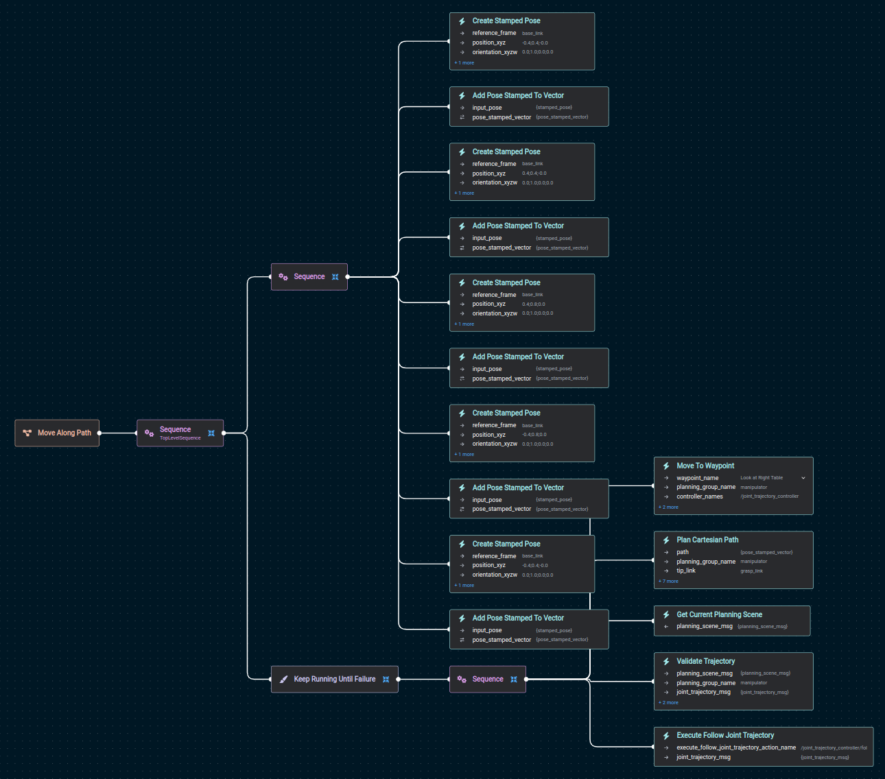
As you can see, the Objective has two main blocks:
- A
Sequenceblock that defines the path to follow, with calls toCreate Stamped PoseandAdd Pose Stamped To Vector. - A
Keep Running Until Failureblock, with calls toMove To Waypoint,Plan Cartesian Path,Get Current Planning Scene,Validate TrajectoryandExecute Follow Joint Trajectory. This will plan and execute the path in a loop.
The following two sections go more in detail into these two blocks.
3. Defining the path to follow
Path waypoints are defined via alternate calls to Create Stamped Pose and Add Pose Stamped To Vector.
More in detail:
Create Stamped Pose: Creates a geometry_msgs/PoseStamped message describing a pose relative to a given reference frame.Add Pose Stamped To Vector: Adds a given geometry_msgs/PoseStamped message to a vector of poses.
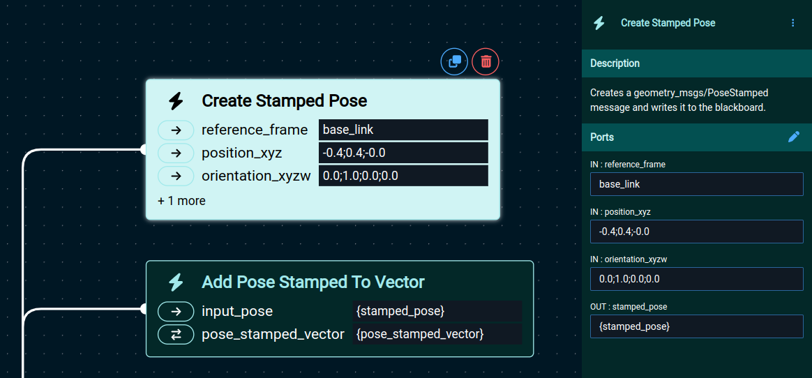
The reference_frame in Create Stamped Pose can be any frame available in the tf tree.
The pose defined in that behavior (position_xyz and orientation_xyzw) will be relative to that reference frame.
Different points along the path can have different reference frames.
They will all be converted to the robot group base frame internally, later in the pipeline.
The actual 3D path is constructed with calls to Add Pose Stamped To Vector, which add the waypoints to a vector (the path), one by one.
4. Planning a joint-space trajectory
The next step is to plan a joint-space trajectory that can follow the 3D path.
That is done with the second block of the Objective, under the Keep Running Until Failure and Sequence decorators.
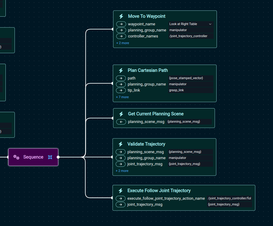
This part starts with a Move To Waypoint Behavior, which moves the robot to an initial joint configuration that faces the right table.
The actual planning of the trajectory (path inverse kinematics) is done with the Plan Cartesian Path Behavior.
Here’s a detailed view of that Behavior and the parameters it accepts.
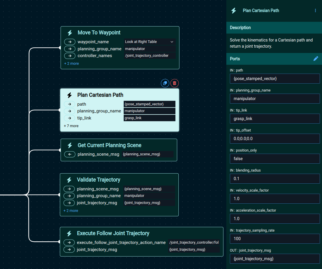
The Plan Cartesian Path Behavior takes the following input and output parameters:
- path: This refers to the path constructed previously via
Create Stamped PoseandAdd Pose Stamped To Vector. - planning_group_name: Specifies which subgroup of the robot will be used to follow the path.
- tip_link: Indicates the specific link in the given subgroup that needs to follow the path, i.e. the end-effector.
- tip_offset: Adds an optional (x,y,z) offset to the given tip_link.
- position_only: Specifies whether to solve for position and orientation, or only position.
- blending_radius: Sets the amount of blending to apply at the corners of the path.
- velocity_scale_factor: Sets the joint-space velocity to use, as a multiplier of the maximum robot velocity.
- acceleration_scale_factor: Sets the joint-space acceleration to use, as a multiplier of the maximum robot acceleration.
- trajectory_sampling_rate: Defines the sampling rate of the output trajectory, in Hz.
- joint_trajectory_msg: Output parameter containing the planned joint-space trajectory.
The Plan Cartesian Path behavior will always use the current robot configuration as the first waypoint in the path.
This will be added internally, and therefore it doesn’t have to be included in the input path.
It must be possible to apply the requested blending_radius at every waypoint in the input path, otherwise an error will be returned. This means that blending_radius needs to be smaller than half the distance between the two closest adjacent waypoints in the path.
The approach used to compute the path inverse kinematics and final trajectory has the following properties:
- Deterministic: Given the same inputs, it will always return the same result.
- Robust to singularities: This method uses a damped least-squares Jacobian inverse, which is robust to singularities.
- Smooth, no jumps: The kinematics are computed incrementally in a way that creates a smooth solution without jumps.
- Respects position joint limits: Position joint limits will be respected at all times along the output trajectory.
- Respects joint-space velocity and acceleration limits: this should be satisfied via MoveIt’s TOTG.
5. Collision-checking the trajectory
The Plan Cartesian Path Behavior does not check for collisions; it only resolves the kinematics.
Therefore, it is necessary to check that the given robot trajectory does not collide with the environment before it is sent for execution.
This can be done with the Validate Trajectory Behavior:
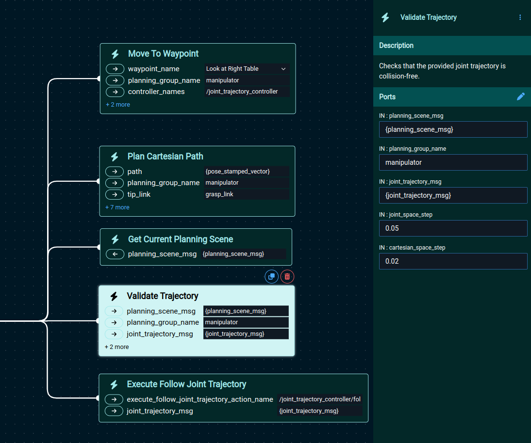
The Validate Trajectory Behavior takes the following inputs:
- planning_scene_msg: A
moveit_msgs/PlanningScenemessage, which contains a description of the obstacles around the robot. - planning_group_name: The planning group that this trajectory uses.
- joint_trajectory_msg: A trajectory message, e.g., the output of
Plan Cartesian Path.
Since trajectories are normally given at the control rate, they can contain thousands of very dense waypoints.
A collision check on a full dense trajectory would be very time consuming.
Therefore, the Validate Trajectory Behavior will first downsample the trajectory at a desired density.
This is given by the joint_space_step and cartesian_space_step input parameters:
- joint_space_step indicates the minimum joint-space distance (L1 norm), in radians, between two adjacent waypoints.
- cartesian_space_step controls the minimum Cartesian-space distance, in meters, between two adjacent waypoints (measured as the Euclidean distance on the translation at the last link of the group).
Both of them are equally important, since a small joint-space step could lead to a large Cartesian-space step on a large robot, which could miss collisions. Similarly, a small Cartesian increment could require large joint-space changes. Therefore it is important to set a meaningful value in both.
You can specify a custom planning scene for collision-checking using the planning_scene_msg input port.
However, if you want to check for collisions against the current planning scene, as sensed by the robot, you can create this input with the Get Current Planning Scene Behavior, as is done in this example Objective.
The Validate Trajectory Behavior doesn’t return anything as output.
It will just fail if a collision is found, or succeed otherwise.
6. Executing a joint-space trajectory
Trajectory execution is done with a call to the Execute Follow Joint Trajectory Behavior.
This Behavior takes a joint-space trajectory as input (output of Plan Cartesian Path) and sends it to a joint-space trajectory tracking controller for execution.
7. Visualizing and understanding errors
The method used to compute the path inverse kinematics is a local method. This means it can only find a solution when it is locally connected in a continuous way, i.e., no large joint-space reconfigurations are required. Similarly, it can’t handle path deviations, i.e. it will try to solve for the exact path, or return a failure if the path can’t be exactly solved. When a failure is returned, an error message will pop-up with the cause of the failure:
- A joint limit was reached: When solving the path requires moving a joint past it position limit, an error message will be returned indicating which joint has reached its limit.
- Path goes out of the reachable space: this means that no joint limits were hit when solving for the path, but still the path couldn’t be solved. It is likely the path goes out of robot feasible workspace.
- Corner rounding can’t be applied: Path waypoints needs to be spaced in such a way that the blending radius can be applied to all the waypoints, otherwise an error will be returned indicating the invalid waypoint.
In case of failure, both Plan Cartesian Path and Validate Trajectory return an MTCSolution debug message in the debug_solution output port.
This message can be passed as input to the WaitForUserTrajectoryApproval objective, which will visualize the portion of the trajectory that is feasible, and give the user the option to accept or reject it.
For example, in this screen capture, the robot is commanded to move in straight line out of the feasible workspace.
The Plan Cartesian Path behavior fails, and that failure is captured by the Fallback node, which then executes the fallback WaitForUserTrajectoryApproval behavior.
The WaitForUserTrajectoryApproval behavior then shows the portion of the path that is feasible.
The user in this case accepts to execute the feasible portion of the path.