Cartesian Path Following
Many applications require moving the arm end-effector along a given path in 3D space. Some examples include welding, grinding, inspection, and door opening.
This how-to guide will walk through a portion of an example grinding Objective that defines a path in 3D space and plans for a robot trajectory that can follow that path.
Launch MoveIt Pro
We assume you have already installed MoveIt Pro to the default install location. Launch the application using:
moveit_pro run -c grinding_sim
1. Run the Grind Machined Part Objective
To get an understanding of what path following means in practice, run the Grind Machined Part Objective.
This Objective makes the tip of a grinding tool follow a rectangular path over the surface of a sample machined part:
2. Objective overview
After running the Objective, open the Behavior Tree to learn how the Objective is defined.
Select the Build tab, click on the Grind Machined Part Objective, and then select Edit.
In this how-to guide, we're going to be focusing on how to save poses for loading, the second half of the
Grind Machine Part Objective, and some additional details on validation and errors in the following sections:
- Saving a vector of poses to a yaml file
- Loading and visualizing a vector of poses from a yaml file
- Planning, previewing, and executing a cartesian trajectory through the loaded poses
- Validation and understanding errors
The following sections go more in detail on these 3 steps.
If you want to learn more about the first part of the Objective in which the machined part object is registered, check out the Object Registration how-to guide.
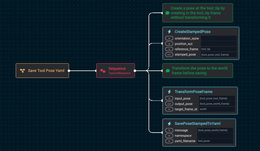
3. Saving a vector of poses to a yaml file
To save poses to a YAML file:
- Move the tool tip to a desired location using the iMarker and Pose Jog control modes while running the
TeleoperateObjective. - Run the
Save Tool Pose YamlObjective when the tool tip is in a desired pose and see thetool_pose.yamlfile gets saved pose in the grinding_sim Objectives directory.
- To save multiple yaml poses in a single yaml file, copy-paste the output from
tool_pose.yamlinto a new file so it won't get overwritten (ex:my_tool_poses.yaml) and insert---before each of the poses. See below for an example:
---
header:
  stamp:
    sec: 0
    nanosec: 0
  frame_id: registered_pose
pose:
  position:
    x: 0.059
    y: 0.152
    z: 0.203
  orientation:
    x: 0.678
    y: -0.678
    z: -0.201
    w: 0.201
---
header:
  stamp:
    sec: 0
    nanosec: 0
  frame_id: registered_pose
pose:
  position:
    x: 0.057
    y: -0.131
    z: 0.203
  orientation:
    x: 0.678
    y: -0.678
    z: -0.201
    w: 0.202
...
You will need to rebuild your workspace to register the new file before it can be loaded by an Objective.
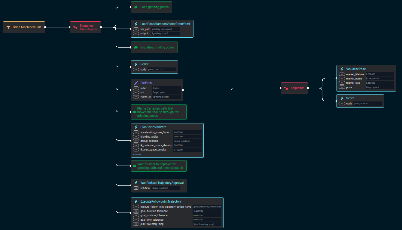
4. Loading and visualizing a vector of poses
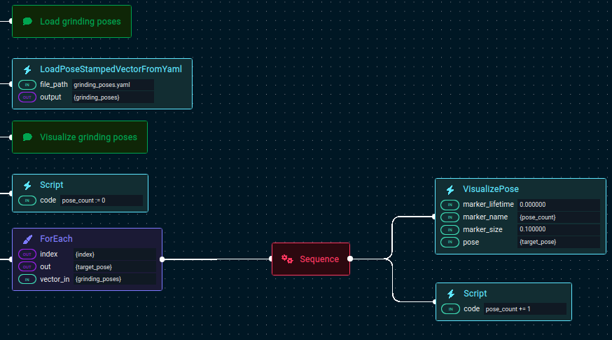
The LoadPoseStampedVectorFromYaml Behavior is used to load desired poses from a yaml file onto the blackboard. Once
loaded, the Objective iterates over the vector using the ForEach block and each pose is visualized using the
VisualizePose Behavior. The Script blocks create and update the pose_count variable which is used to uniquely name
each pose in the VisualizePose marker_name port so they do not overwrite each other.
5. Planning, previewing, and executing a Cartesian path
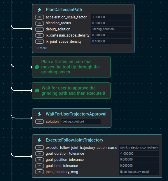
- The next step is to plan a joint-space trajectory that can follow the 3D Cartesian path. This planning is done with
the
PlanCartesianPathBehavior. The pose vector that was loaded onto the blackboard is provided to the Behavior on thepathinput port. For a more detailed view of that Behavior and the parameters it accepts, refer to the UI.
The PlanCartesianPath Behavior will always use the current robot configuration as the first waypoint in the path.
This will be added internally, and therefore it doesn't have to be included in the input path.
It must be possible to apply the requested blending_radius input port to PlanCartesianPath at every waypoint in the
input path, otherwise an error will be returned. This means that blending_radius needs to be smaller than half the
distance between the two closest adjacent waypoints in the path.
The PlanCartesianPath Behavior does not check for collisions; it only resolves the kinematics. In the case that the
trajectory should be collision checked with the planning scene before execution, the ValidateTrajectory Behavior can
be used. Check the next section for more details.
The approach used to compute the path inverse kinematics and final trajectory has the following properties:
- Deterministic: Given the same inputs, it will always return the same result.
- Robust to singularities: This method uses a damped least-squares Jacobian inverse, which is robust to singularities.
- Smooth, no jumps: The kinematics are computed incrementally in a way that creates a smooth solution without jumps.
- Respects position joint limits: Position joint limits will be respected at all times along the output trajectory.
- Respects joint-space velocity and acceleration limits: this should be satisfied via MoveIt's TOTG.
- Once the path is planned, the trajectory is previewed in the UI using the
WaitForUserTrajectoryApprovalBehavior and the user is given the option to approve or reject it.
- Trajectory execution is done with a call to the
ExecuteFollowJointTrajectoryBehavior. This Behavior takes a joint-space trajectory as input (output ofPlanCartesianPath) and sends it to a joint-space trajectory tracking controller for execution.
6. Validation and understanding errors
Validation
In the case that the trajectory should be collision checked with the planning scene before execution, the
ValidateTrajectory Behavior can be used. For a detailed view of the Behavior and the parameters it accepts, refer to
the UI.
Since trajectories are normally given at the control rate, they can contain thousands of very dense waypoints. A
collision check on a full dense trajectory would be very time-consuming. Therefore, the ValidateTrajectory Behavior
will first downsample the trajectory at a desired density. This is given by the joint_space_step and
cartesian_space_step input parameters. Both of which are equally important, since a small joint-space step could lead
to a large Cartesian-space step on a large robot, which could miss collisions. Similarly, a small Cartesian increment
could require large joint-space changes. Therefore, it is important to set a meaningful value in both.
You can specify a custom planning scene for collision-checking using the planning_scene_msg input port. However, if
you want to check for collisions against the current planning scene, as sensed by the robot, you can create this input
with the Get Current Planning Scene Behavior, as is done in this example Objective.
The ValidateTrajectory Behavior doesn't return anything as output. It will just fail if a collision is found, or
succeed otherwise.
Understanding errors
The method used to compute the path inverse kinematics is a local method. This means it can only find a solution when it is locally connected in a continuous way, i.e., no large joint-space reconfigurations are required. Similarly, it can't handle path deviations, i.e. it will try to solve for the exact path, or return a failure if the path can't be exactly solved. When a failure is returned, an error message will pop-up with the cause of the failure:
- A joint limit was reached: When solving the path requires moving a joint past it position limit, an error message will be returned indicating which joint has reached its limit.
- Path goes out of the reachable space: this means that no joint limits were hit when solving for the path, but still the path couldn't be solved. It is likely the path goes out of robot feasible workspace.
- Corner rounding can't be applied: Path waypoints needs to be spaced in such a way that the blending radius can be applied to all the waypoints, otherwise an error will be returned indicating the invalid waypoint.
In case of success or failure, both PlanCartesianPath and ValidateTrajectory return an MTCSolution debug message
in the debug_solution output port. In the case of failure, the debug solution will contain the portion of the
trajectory that is feasible. This message can be passed as input to the WaitForUserTrajectoryApproval Behavior as
shown in the last section for visualization and approval in the UI.
For example, in this screen capture, the robot is commanded to move in a straight line out of the feasible workspace.
The PlanCartesianPath Behavior fails, and that failure is captured by the Fallback node, which then executes the
fallback WaitForUserTrajectoryApproval Behavior. The WaitForUserTrajectoryApproval Behavior then shows the portion
of the path that is feasible. The user in this case accepts to execute the feasible portion of the path.
7. Tracking a path with multiple end-effectors
The PlanCartesianPath Behavior can also be used to track a path with multiple end-effectors, by providing multiple "tip links" as input.
In this case, all the given tip links will move synchronously along the same path, keeping their initial relative pose with respect to the path origin.
An example can be found in the multi_arm_sim config:
moveit_pro run -c multi_arm_sim
After bringing up MoveIt Pro, run the Multi-tip Path IK Example Objective.
You should see two arms moving to an initial pose, and them moving synchronously along a square path.