Calibrate the Seeed reBot B601-RS
This guide takes a new B601-RS and its Star Arm 102 leader from a working setup to an installation whose joints, cameras, and gravity model match the physical arm. Work through the sections in order: later sections rely on the earlier ones. Skip the sections for hardware you do not have: an installation based on rebot_b601_rs_hw alone has no scene camera, so it skips sections 4 and 6, and it keeps the stock gravity model in section 7.
Turn torque off only at HOME (Zeroed Rest), where the arm rests on its built-in stops; anywhere else it falls. A fresh arm powers up with torque off: support it by hand whenever it is out of its folded rest pose. Only one program may own the CAN bus: stop the MoveIt Pro Runtime before you use a Seeed tool, and never use a vendor tool on an enabled motor, because closing its connection can disable that motor. Before every Runtime stop or restart on this page, run Relax at HOME and confirm that it succeeded. Calibration Objectives move the arm, so run them only after the physical package launches and Relax at HOME succeeds, as in Launch the Physical Robot Configuration Package and Return HOME and Turn Torque Off.
Where Calibrated Values Go
The workspace ships two kinds of robot configuration package. rebot_b601_rs_hw is the stock arm: the motors, the Gemini 305 wrist camera, and the optional Star Arm 102 leader. The cube-stacking application package picknik_boston_rebot_b601_rs_hw inherits it and adds a fixed Luxonis OAK-D scene camera, a world frame on a table mat, a depth correction for that camera, and the tools that fit a gravity model. Both ship nominal values for every per-unit setting, so they build and plan, but perception and gravity compensation are only as good as the calibration you add.
Keep every calibrated value in a child robot configuration package of the one you run, never in the shipped packages. A calibration belongs to one physical arm, leader, or camera, and a value written into a shipped package would silently apply to every other installation. See robot configuration package inheritance. The child lists only what it changes, because urdf_params merge by key:
based_on_package: picknik_boston_rebot_b601_rs_hw  # or rebot_b601_rs_hw without a scene camera
hardware:
  additional_driver_launch_file:
    package: my_rebot_hw
    path: launch/rebot_drivers.launch.py
  robot_description:
    urdf_params:  # add each entry only once you have measured it; until then the parent's nominal value applies
      - world_to_base_xyz: "x y z"
      - world_to_base_rpy: "roll pitch yaw"
      - scene_camera_xyz: "x y z"
      - scene_camera_rpy: "roll pitch yaw"
      - wrist_camera_color_optical_xyz: "x y z"
      - wrist_camera_color_optical_rpy: "roll pitch yaw"
ros_global_params:  # only with a Star Arm 102 leader; see below
  rebot_leader_enabled: true
  rebot_leader_port: "/dev/serial/by-id/<your leader>"
  rebot_leader_calibration_file: "<absolute path to your leader file>"
The cube-stacking application package enables the leader. A child of it without a leader sets rebot_leader_enabled: false instead of the three leader lines. It also copies the no-leader rebot_check_leader_idle.xml and rebot_notify_leader_home.xml from the stock objectives/ of rebot_b601_rs_hw into its own objectives/, and lists that directory in its objective_library_paths under a new key, such as my_no_leader_objectives: for each Objective file name, the last library wins, and only a new key is appended after the inherited libraries. A key the parent already uses keeps the parent's place in the list and replaces the parent's directory. The two copies then replace the leader versions. Do not list the whole stock objectives/ directory there, because it would also replace application Objectives that share a name with stock ones. Without the two copies, Relax at HOME waits on a leader bridge that never starts and refuses.
The camera serials and the scene depth scale are launch arguments of the drivers, so the child also gets its own driver launch file, named in additional_driver_launch_file above. It includes the parent's driver launch and passes those arguments on:
from pathlib import Path

from ament_index_python.packages import get_package_share_directory
from launch import LaunchDescription
from launch.actions import IncludeLaunchDescription
from launch.launch_description_sources import PythonLaunchDescriptionSource


def generate_launch_description():
    parent = Path(get_package_share_directory("picknik_boston_rebot_b601_rs_hw"))
    return LaunchDescription(
        [
            IncludeLaunchDescription(
                PythonLaunchDescriptionSource(str(parent / "launch/rebot_drivers.launch.py")),
                launch_arguments={
                    # Empty selects the first camera; set each serial in section 3.
                    "wrist_camera_serial_number": "",
                    "scene_serial_no": "",
                    # 1.0 leaves depth unchanged; set the measured factor in section 6.
                    "scene_depth_scale": "1.0",
                }.items(),
            )
        ]
    )
A child of rebot_b601_rs_hw sets only the wrist camera entries, plus the leader entries if it has a Star Arm 102, and includes that package's launch/rebot_drivers.launch.py. The stock leader is off by default; to enable it, follow the stock package's README. Install every directory the child adds in its CMakeLists.txt, listing only the ones it has, for example install(DIRECTORY config launch objectives DESTINATION share/${PROJECT_NAME}), plus description if you copy the description for section 7. Rebuild the workspace and restart the Runtime after every change. The sections below say which entry each calibration fills in.
1. Zero the Follower Motors
Every joint angle MoveIt Pro uses is measured from each motor's stored zero. HOME is all seven joints at 0 rad, and the joint limits, the robot model, the Relax at HOME admission check, and the leader mapping all assume that 0 rad is Seeed's zero pose. If a motor's zero is off, the model no longer matches the arm: collision checks pass for motion that hits the arm or the bench, a limit can sit beyond a hard stop, and HOME is a pose where the arm does not rest on its own, so Relax at HOME either refuses or turns torque off where the arm can sag. The arm only needs zeroing once after assembly, and again after a motor is replaced or a joint slips.
Seeed zeroes the arm with MotorBridge Studio, following its Getting Started guide. Its zero pose is the photo in Seeed's LeRobot guide: the arm folded and resting, the jaw pointing forward and fully closed. It matches the solid arm in the diagram below.
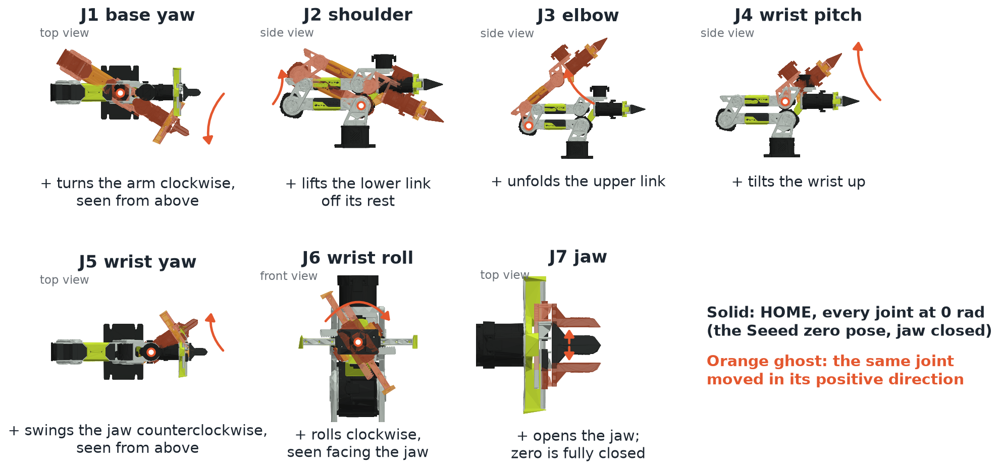
The diagrams on this page are rendered from the stock robot description, with Seeed's reBot-DevArm meshes (CERN-OHL-W-2.0). Each panel in this one shows HOME and, tinted, the same arm with one joint moved in its positive direction. These are the directions MoveIt Pro expects; a joint that reads the other way on your arm points at a wiring or assembly fault, not a calibration.
- If the arm has been running under MoveIt Pro, run
Relax at HOMEand confirm that it succeeded before you stop the Runtime. If it refuses, torque stays on: follow Return HOME and Turn Torque Off, and do not start MotorBridge until torque is off. Then stop the MoveIt Pro Runtime, and keep the MoveIt Pro driver off the bus until zeroing is done. - Start the MotorBridge gateway and MotorBridge Studio as Seeed's guide describes, select the RobStride reBot arm model, and scan. All seven motors must be online, with IDs 1–7. Do not rewrite motor IDs on an assembled arm.
- With torque off, support the arm and move it by hand into the zero pose. Close the jaw gently with nothing between the fingers. Compare the wrist with Seeed's photo by its asymmetric parts, such as where the wrist cable connectors sit, not only by its outline: the wrist can look right half a turn away from zero.
- Read all seven positions, one joint at a time. MotorBridge Studio's Zero All requires every joint within ±0.08 rad of its current zero, and so does the HOME check in MoveIt Pro.
- A joint near ±3.1 rad is likely half a turn away from zero. Check the cable route before you turn anything, and turn only while the cables stay slack.
- A joint near ±6.3 rad is counting one extra full turn: the pose can look right while the reading is a turn off. Do not turn it another turn. On our test bench, unplugging and replugging the wrist-roll motor with the power off cleared an extra turn.
- Use MotorBridge Studio's force option only after you have confirmed the physical pose against Seeed's photo, never to get past a reading you cannot explain.
- Click Zero All and confirm. MotorBridge Studio zeroes and stores each motor in turn. Check the result line for each of the seven motors, not only the summary, and confirm that every joint now reads 0.000.
- Initialize the motor control parameters as Seeed's guide describes: Read Parameters, Apply Default Template, then Write Parameters with the arm resting at the zero pose. The write succeeded when MotorBridge Studio reports that the readback matches.
- Close MotorBridge, power-cycle the arm with it resting at the zero pose, and read the positions again. Every joint must still be within 0.08 rad of zero; otherwise the zero was not stored.
- Check zero and signs the way MoveIt Pro sees them: launch the torque-disabled inspection package from the setup guide, confirm
/joint_statesreads near zero for all seven joints, then move one joint at a time by a small amount and compare the sign with the diagram. Support the arm throughout and return it to the zero pose after each joint. At the zero pose, J5 is against a stop: raise J4 a little before you swing J5. Opening the jaw reads positive, and its full stroke is several radians, because the reading is the motor turning through the jaw drive.
Seeed's LeRobot follower calibration re-zeroes every motor at the pose the arm is in when you confirm its prompt. MoveIt Pro does not need it; if you run it, run it only at the zero pose and repeat step 8 afterwards.
2. Calibrate the Star Arm 102 Leader
Mirror reBot Leader commands each follower joint to the matching leader joint angle, so the leader's zero must be the same physical pose as the follower's. A leader zero that is off by a few degrees makes the follower hold that offset in every pose. A larger error makes Mirror refuse to start: its engage check refuses an arm joint more than 0.6 rad from the follower and names the joint and its signed offset.
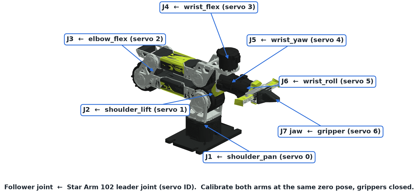
The leader uses Seeed's stored-origin calibration: calibrating writes each servo's origin into the servo itself and saves a JSON file that records the servo IDs and that convention, with zero homing offsets. The file the workspace ships, rebot_arm_102_leader.json, came from one Star Arm 102. Because the origin lives in that unit's servos, the shipped file does not calibrate your leader. Calibrate your own leader once, and keep the file it produces with your installation.
-
Clamp the leader to the table outside the follower's reach, power it from its own 12 V supply, and connect its USB cable to the host. Never connect it to the follower's 48 V supply or to the CAN bus. Note its stable
/dev/serial/by-id/...name, and give the account that opens itdialoutaccess, as the leader-follower demo describes. -
Run
Relax at HOME, then stop the MoveIt Pro Runtime, so the leader reader releases the serial port. Install Seeed's LeRobot environment with therebot_arm_102_leaderteleoperator, as Seeed's LeRobot guide describes. -
Pose the leader at Seeed's leader zero pose, shown in the same guide, with its gripper closed. It is the same folded pose as the follower's zero.
-
Hold the leader still and run Seeed's calibration, with your port and a name for this unit:
lerobot-calibrate \--teleop.type=rebot_arm_102_leader \--teleop.port=/dev/serial/by-id/<your leader> \--teleop.id=<your leader name>If a file for that name already exists, the tool offers to reuse it, which writes nothing: enter
cto calibrate again. It writes the origins into the servos and saves<your leader name>.jsonunder~/.cache/huggingface/lerobot/calibration/teleoperators/rebot_arm_102_leader/. -
Check the result with the reading check in Seeed's guide: at the zero pose every joint reads 0, and each joint's reading changes only when you move that joint. If a joint moves the wrong way, do not recalibrate: the joint directions are fixed in the leader reader, not in the calibration.
-
Copy the file into your child robot configuration package, for example
config/leader_calibration/<your leader name>.json, and setrebot_leader_calibration_fileandrebot_leader_portin itsros_global_params. A relative path resolves against therebot_b601_rs_hwpackage, so give the absolute path as the Runtime sees it: the workspace is mounted at~/user_wsof the Runtime user, andmoveit_pro shelllets you check the path withls.
MoveIt Pro refuses a file that does not list all seven joints with servo IDs 0–6, zero homing offsets, drive_mode 0, and range_min below range_max, so a file from another convention fails at launch instead of moving the follower. The values of range_min and range_max are placeholders; MoveIt Pro uses its own joint ranges. If the leader loses power or its cable during use, stop Mirror reBot Leader, let the follower return HOME, reconnect the leader, and restart the Runtime: the reader does not reopen its port.
The final check is the leader-follower demo: with the follower at HOME and the leader held near the same pose, Mirror reBot Leader engages without a mismatch refusal, and each follower joint follows its leader joint in the same direction. Once the follower's zero has passed section 1, a small steady offset on one joint means the leader was not at its zero pose during calibration: calibrate the leader again rather than adjusting the follower.
3. Pin the Camera Serials
Each camera driver opens the first camera it finds that it can drive, and the stock wrist launch starts the Orbbec driver on the first Orbbec camera of any model. With two cameras that share a driver on one host, such as a Gemini 305 wrist camera and a Gemini 335 scene camera, which one is "first" can change after a reboot or a replug, and a camera calibration then applies to the wrong camera without any warning: the stream looks normal, but every position measured from it is wrong. Pin the serials even with one camera per driver, so that a camera added later cannot take another's place.
The application package drives only a Luxonis OAK-D scene camera, whose serial is its MX ID, and scene_serial_no and scene_depth_scale apply only to that driver. A different scene camera, such as the Gemini 335 that the setup guide recommends, needs its own driver launch in your child package. The application's Objectives read the color image on /scene_camera/color/image_raw, its camera info on /scene_camera/color/camera_info, and a point cloud aligned to the color camera on /scene_camera/depth/color/points, all in scene_camera_color_optical_frame, so remap that driver's outputs to those names and turn off its own TF publishing: the robot description places the camera frames. Also pass enable_scene_camera as false to the parent's driver launch, so that an OAK-D left connected does not start and publish on the same topics. Section 4 applies to it as written; this section and section 6 then use that driver's own serial and depth settings, where it has them.
- Read each camera's serial number with only that camera attached and the serial launch arguments empty, including when you replace a camera whose serial is already pinned: a pinned serial keeps the driver from opening any other camera. Start the Runtime, read the serial from the driver's startup log, stop the Runtime, and repeat for the next camera. With two cameras that share a driver attached, the wrist driver can open the scene camera and log its serial, so a log read with both attached can record the two swapped.
- Set
wrist_camera_serial_numberand, for the scene camera,scene_serial_noin your child package's driver launch file. The launch argument overrides thewrist_camera_serial_numberdefault in the stockconfig/wrist_camera.yaml; leave that shipped file unchanged. - Label each camera with its serial. A camera calibration belongs to one physical camera and its mount: after you swap a camera or rebuild its mount, calibrate it again.
4. Place the Base and the Scene Camera
The cube-stacking application package places everything in a world frame on the table mat: the mat's top surface is z = 0, and the robot base and the scene camera are fixed joints from that frame. The planning scene's mat and wall boxes, the cube search area, and the place spots are all given in the same frame. If the base placement is off, the arm plans to places that are not where the mat is; if the scene camera pose is off, every object it sees is shifted or tilted by the same error, so a grasp misses.
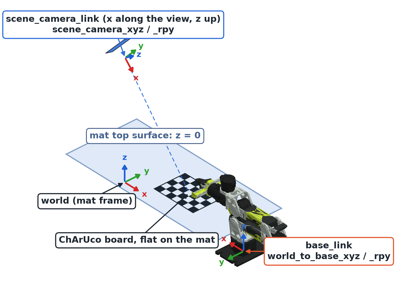
The diagram shows the frames, not a measured layout. Set up the bench as in the cube-stacking layout, or change its scene boxes and areas to match your bench.
Base. Use the world frame of the cube-stacking layout, since its planning scene boxes, cube search area, and place spots are fixed in it: z = 0 on the mat's top surface, and the mat centered at (0.133, 0.160) m with its long side along world x. If your bench differs, change those scene boxes and areas to match it first, as the layout page describes. base_link lies on the arm's mounting surface, directly below the J1 axis, with x pointing the way the jaw points at HOME. Measure its position and yaw on the mat, and set world_to_base_xyz and world_to_base_rpy. Keep roll and pitch at zero when the base is bolted level. If the mat lies on the same table as the base, z is minus the mat's thickness.
Scene camera. The scene camera pose comes from one image of a ChArUco board lying flat on the mat at a measured pose. Print the board as Camera Calibration describes. The reference bench used 7 × 5 squares of 35 mm with 26 mm markers, dictionary DICT_4X4_50, which fits on A4 and also suits the wrist camera in the next section.
- Lay the board flat on the mat, edges parallel to the mat's axes, fully in the scene camera's view.
- Make an Objective that runs
GetCameraInfoandGetImageon the scene camera's color topics, thenDetectCharucoBoard. Set itsboardport in the board editor to your print, for the reference board 7 × 5 squares, a 0.035 m square, and a 0.026 m marker, dictionaryDICT_4X4_50: the square size sets the scale of the pose, so a wrong value moves the camera along its view. Itsboard_poseoutput is the board frame in the camera's optical frame, estimated with the camera's factory intrinsics. Save it withSavePoseForUrdf. - Find the board frame on your print: draw
board_posewithVisualizePoseand open the scene camera image with Show 3D Overlay. The frame is drawn in the camera's own optical frame, so it lands on the board's origin corner in the image whatever the camera's current pose in the description. Measure that corner's position on the mat and the direction of each board axis in the world frame. - Compose the camera pose in the world: world to optical frame is world to board times the inverse of
board_pose.scene_camera_linkfollows REP 103, with x along the view and z up, and the optical frame sits at a fixed rotation of roll −π/2, yaw −π/2 from it, so remove that rotation to getscene_camera_link. Setscene_camera_xyzandscene_camera_rpy. - Rebuild and restart, then check the alignment in the camera pane: the robot model and the mat box drawn over the scene image line up across the whole image.
Check both placements with Locate reBot Cubes, which does not move the arm: place the red and the blue cube apart on the mat, and each cube's reported position matches a tape measurement to a few millimeters. It locates cubes from the color image and the calibrated camera pose, not from depth, and places each cube top 0.05 m above the mat by construction, so it checks position only. After the wrist calibration in the next section, the base gets a second check.
5. Calibrate the Wrist Camera Hand-Eye
The stock transform from gripper_end to wrist_mounted_camera_color_optical_frame is a nominal estimate from the mount's CAD. Printed mounts, screws, and camera housings vary, and the error grows with distance: a mount one degree off moves a point 0.4 m from the camera by about 7 mm. Calibrate the transform before you use the wrist camera to measure anything.
Wrist hand-eye calibration needs orbbec_camera 2.10.6 or newer (earlier versions mislabel the Gemini 305 distortion model). With an older driver, the calibration cannot collect samples. Check the installed version from moveit_pro shell with ros2 pkg xml orbbec_camera --tag version. If it is older than 2.10.6, postpone this section until your Runtime image provides 2.10.6 or newer: the rest of the guide does not depend on it.
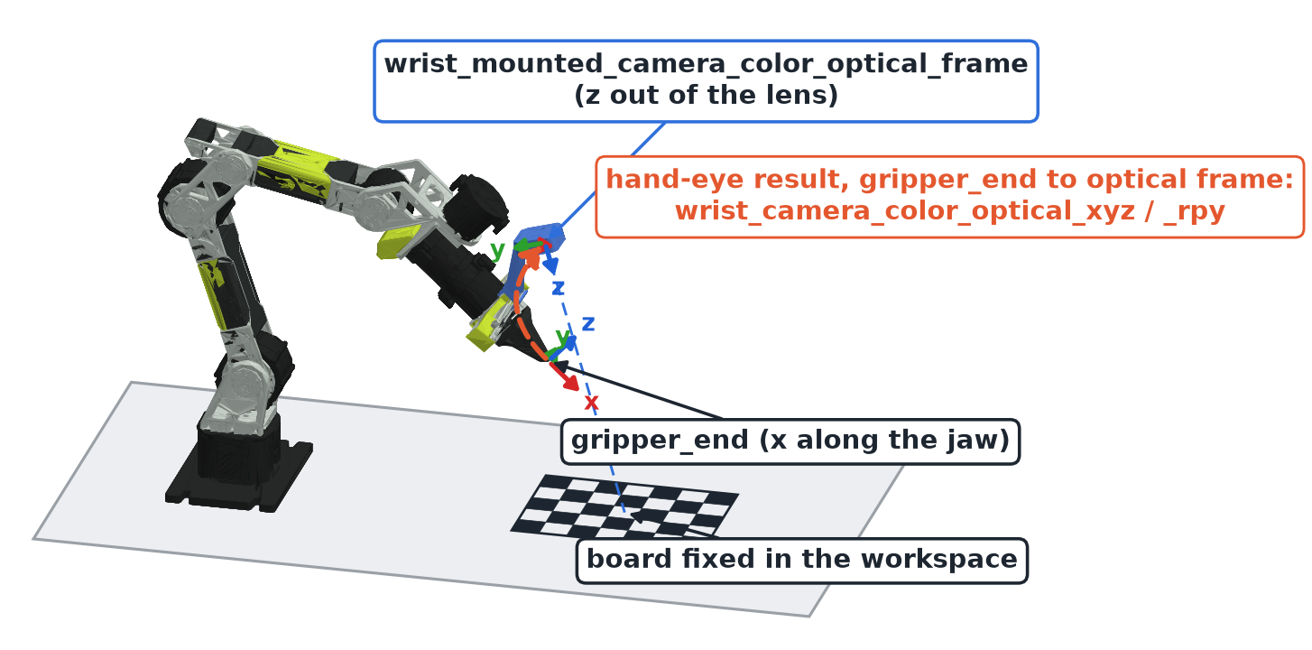
The calibration uses MoveIt Pro's eye-in-hand Subtree; read Camera Calibration first. On the reBot:
- Fix the board flat on the mat where the wrist camera sees it from poses near the arm's working area. Leave it where the scene camera calibration measured it if you want the base check below.
- Delete any waypoints whose names start with
calibrationfrom earlier runs in the Desktop App: the Subtree visits every waypoint with that prefix. Then save the calibration waypoints by hand: jog the arm withTeleoperateto each view and save it ascalibration_01,calibration_02, and so on.Generate Calibration Waypointsexpects the camera to look along the end effector frame's z axis, and the reBot's camera does not look alonggripper_endz. Save 10 or more views that keep the whole board in the image and rotate the camera between views about more than one axis, using J1, J4, J5, and J6. Large rotations between views matter most: on our test bench, a solve from small rotations was off by more than a centimeter. Avoid views with the arm stretched out: long holds there heat the shoulder motor. - Make an Objective that calls
Calibrate Eye In Hand Camerawith the wrist camera's raw color image and camera info topics under/wrist_mounted_camera,camera_namewrist_mounted_camera,joint_group_namemanipulator,end_effector_framegripper_end,base_framebase_link, and your board. The stock wrist launch publishes no point cloud, and the Subtree ends with a point cloud snapshot, so Duplicate the Subtree and remove its snapshot nodes (ResetVector,Capture Camera Point Cloud,MergePointClouds, andSendPointCloudToUI) in your copy. The copy still checks thatpoint_cloud_topicis set, so give it any name. - Run it from HOME with the area clear, and return HOME afterwards. Read the residuals in the Alert Sidebar: a good solve agrees across views to a few millimeters and well under a degree. Do not use a result the Objective warns about.
- The solve's
calibrated_camera_poseis the optical frame ingripper_end, which is exactly the joint thatwrist_camera_color_optical_xyzandwrist_camera_color_optical_rpyset. Write it out withSavePoseForUrdf, copy the values into your child package, rebuild, and restart. - After the restart, confirm that the Runtime loaded the new transform: from
moveit_pro shell,ros2 run tf2_ros tf2_echo gripper_end wrist_mounted_camera_color_optical_framemust print the values you saved in step 5. A repeat solve cannot show this, because the solve does not read the configured transform. Then check the result in the camera pane overlay.
The solve also reports calibrated_board_pose, the board in base_link. With the board where you measured it for the scene camera, carry that pose into the world frame through your base placement and compare it with your measurement. The two agree within a few millimeters when the base placement is right; if they do not, correct the base from the board rather than from the tape.
6. Correct the Scene Depth Scale
The cube-stacking Objectives confirm each stack from the scene camera's depth, and a stereo camera's depth can read long or short by a constant fraction. Every point then sits too far or too near along its camera ray: the mat appears below or above z = 0, cube tops read too low or too high, and a stack check fails on a good stack or passes a bad one. The application package multiplies every OAK-D depth by scene_depth_scale before it builds the point cloud. With a different scene camera, scene_depth_scale has no effect: measure the error with step 1 and correct it in that camera's own driver launch, if its driver offers a depth scale, or skip this section. The default, 1.0, leaves depth unchanged. Measure the factor after the scene camera pose is calibrated, because the measurement relies on it.
- Set
scene_depth_scaleto 1.0, rebuild, and restart, so the measurement starts from unscaled depth. With the mat empty, view the scene point cloud in the 3D Visualizer and find the height of the mat points in the world frame. It should be z = 0. - If the mat reads at height
z_mat, negative when the depth reads long, and the camera's optical frame isHabove the mat, set the scale toH / (H - z_mat). For example, a camera that reads 4% long puts the mat at-0.04 Hand needs 0.96. The launch accepts factors from 0.5 to 1.5. - Set
scene_depth_scalein your child package's driver launch file, rebuild, and restart. - Check in the point cloud that the mat now reads z = 0 and that the top of a 100 mm stack of two cubes reads 100 mm.
7. Fit the Gravity Model
The motors run as springs around the commanded position. Without gravity feedforward, each loaded joint settles short of its target by its load divided by its stiffness: the arm sags, motion can drift past the trajectory controller's path tolerance and abort, and Mirror reBot Leader follows with a droop. The gravity compensation controller adds the torque that the robot model predicts gravity needs, so the springs only correct the remaining error. The same model holds the arm up during Start Gravity Comp and Record reBot Motion, where the stiffness is zero: there, any model error makes the arm sink or rise.
The stock model uses the nominal masses from the robot description, unit gains, and the native jaw as its payload. It works with the stock gains, and it is the right starting point. It does not know your camera, mount, and cables, and the nominal masses are not measured. Fitting a model needs the cube-stacking application package picknik_boston_rebot_b601_rs_hw, which contains Collect reBot Gravity Data and scripts/fit_gravity.py. An installation based on rebot_b601_rs_hw alone keeps the stock gravity model. To fit a model to your arm with the application package:
- Run
Collect reBot Gravity Data, following the collection runbook. It moves through 48 named poses from HOME with the jaw empty and closed, and records joint effort at each pose after it settles. Keep the leader and teleoperation idle and the bench clear. Several poses lean the arm back and load the shoulder motor near or beyond its rated torque, so watch its temperature; if a motor reaches 100 °C, the thermal guard tries to return the arm HOME, but a motor fault or lost joint feedback can stop it; if the arm does not reach HOME, follow the runbook's supervised recovery. - Fit the recordings offline with
scripts/fit_gravity.pyfrompicknik_boston_rebot_b601_rs_hw. It takes each run's recording and health bags (--dataset RECORDING_BAG HEALTH_BAG) and a new--outputdirectory, holds out every fifth pose, and writes the fitted inertial origins and a report of the torque error on the held-out poses, with the nominal model for comparison. Adopt the fit only if it lowers the held-out error on J2–J4. The report's nominal model leaves out the jaw payload that the stock controller adds, so it is not exactly the stock controller's error: confirm the improvement on the arm with the checks in step 4. On our test bench, an earlier 24-pose fit cut the held-out error on J2–J4 by a factor of three to six, and left J1, J5, and J6 about where the nominal model had them. - Load the fit from your child package. The application package's description reads
config/gravity/identified_first_moments.yamlnext to itself, so a child that only setsboston_gravity_fit: truestill loads the shipped nominal values, with no warning.- Copy
description/rebot.urdf.xacroandconfig/gravity/identified_first_moments.yamlfrom the application package into your package, in the same relative layout. In the copied description, change theoffice_geometry.xacroinclude to$(find picknik_boston_rebot_b601_rs_hw)/description/office_geometry.xacro. - Write the fitted inertial origins from
gravity_calibrated.urdfin the fit's output directory into your copy ofidentified_first_moments.yaml. - Point
hardware.robot_description.urdfat your copied description, and setboston_gravity_fit: trueinurdf_params. - Copy
config/control/rebot.ros2_control.yaml, pointros2_control.configat your copy, and set thegravity_compensation_controllergains and payload for the fit. The fit's predictions and error report assume a gain of 1, so use 1 on every joint you adopt the fit for; a joint with gain 0 gets no gravity torque, and any other gain needs its own validation. A fit absorbs the jaw, camera, and cables, so it usespayload_mass: 0; keeping the nominal jaw payload would count them twice.
- Copy
- Rebuild and restart, then confirm that the fit loaded: the link inertial origins in the Runtime's
/robot_descriptionmust match your fitted values. Then check the sag at HOME and at theRaisedwaypoint, and the float ofStart Gravity Compwith the arm supported, before you rely on it.
The fitted origins are a gravity-equivalent model, not measured centers of mass, and they are only valid for the real arm: the description refuses them for mock and simulation. Refit after you change anything the arm carries, such as the camera, its mount, or the cable routing. Gravity calibration shows a worked fit and its limits.