Create MuJoCo Files
The MoveIt Pro Simulator uses MuJoCo as its underlying simulation engine. This means in order to set up the MoveIt Pro Simulator, you must create a MuJoCo Modeling XML File (MJCF) that defines the robot and the environment. The easiest way to create this file is by starting with your existing URDF file.
This how-to guide will walk through the URDF to MJCF migration process.
We will be using our example_robot_sim package from previous guides, but there are many more examples in https://github.com/PickNikRobotics/moveit_pro_example_ws/.
To learn more about the MJCF spec, we recommend these references:
If you are following this guide with example_robot_ws, your workspace should look like branch step8.
Retrieve the rendered URDF of the robot
This guide assumes you generate a URDF file for your robot from a xacro file. If you already have a URDF file, you can skip to the next section.
You can generate a rendered URDF file from the non-MuJoCo MoveIt Pro site config using the following commands.
-
Run the non-MuJoCo MoveIt Pro site config:
moveit_pro run -v -c example_robot_mock -
Enter the MoveIt Pro Docker container:
moveit_pro shell -
Copy the auto-generated URDF file from the
/robot_descriptiontopic to a file.ros2 topic echo --once --field data --full-length /robot_description | head -n -1 > ~/user_ws/robot_description.urdf -
Exit MoveIt Pro.
Prepare the rendered URDF for conversion
Copy your robot_description.urdf file into the example_robot_sim/mjcf directory.
cd ~/example_robot_ws
mkdir src/example_robot_sim/mjcf/assets -p
mv robot_description.urdf src/example_robot_sim/mjcf/assets/
Use implicitfast integration
The default Euler integration typically does not perform well for the instructions in this guide. Add xml to your URDF to use implicitfast integration with multi contact consideration, which will propagate to the generated MJCF.
<?xml version="1.0" ?><mujoco model="r6_2f_proto1">
  <mujoco>
    <option integrator="implicitfast">
      <flag multiccd="enable" />
    </option>
  </mujoco>
Prepare mesh files
If the visual files are currently in the .dae format, use Blender or Meshlab to convert them to .obj files. The .stl file format is also accepted by MuJoCo.
- Note 1: Make sure the axes are aligned correctly when you export the
.objfiles from Blender. You may need to change the "Up Axis" to Z and the "Forward Axis" to X when you export. - Note 2: May need to use the obj2mjcf tool to create
.objfiles that have material information embedded in them. This tool can also perform convex mesh decomposition if needed.
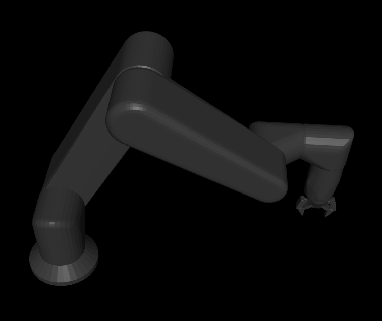
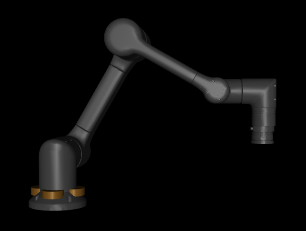
Our example arm and Robotiq description use .dae files for the visual meshes.
For now we will modify all the <visual> elements using .dae files to use the same .stl mesh files as the <collision> elements.
For example:
  <link name="base_link">
    <visual>
      <origin rpy="0 0 0" xyz="0 0 0"/>
      <geometry>
        <!-- <mesh filename="package://example_arm_description/meshes/visual/link_0.dae"/> -->
        <mesh filename="package://example_arm_description/meshes/collision/link_0.stl"/>
      </geometry>
    </visual>
    <collision>
      <origin rpy="0 0 0" xyz="0 0 0"/>
      <geometry>
        <mesh filename="package://example_arm_description/meshes/collision/link_0.stl"/>
      </geometry>
    </collision>
  </link>
This command will make all the modifications for you:
cd ~/example_robot_ws
sed -i -E 's|meshes/visual/2f_85/([^"]+)\.dae|meshes/collision/2f_85/\1.stl|g' src/example_robot_sim/mjcf/assets/robot_description.urdf
Preserving link:body mapping when using fixed joints
When MuJoCo compiles a URDF model, it will by default merge "child" geometry connected via a fixed joint into its parent geometry children for performance optimization.
The transforms are preserved in the <geom> elements, but there is no longer a 1:1 mapping from URDF <link> to MJCF <body> elements.
This can cause complications if you wish to use certain <body> Mujoco features such as <exclude> that are no longer effective with the merged geometries.
For example this URDF structure excerpt:
<link name="world"/>
<link name="base_link">
  <collision>
    <geometry>
      <mesh filename="base_link.stl"/>
    </geometry>
  </collision>
</link>
<joint name="world_to_base_fixed_joint" type="fixed">
  <origin xyz="1 0 0" rpy="0 0 0"/>
  <parent link="world"/>
  <child link="base_link"/>
</joint>
<link name="link_1">
<joint name="base_to_l1_fixed_joint" type="fixed">
  <parent link="base_link"/>
  <child link="link_1"/>
</joint>
<link name="link_2">
<joint name="l1_to_l2_revolute_joint" type="revolute">
  <parent link="link_1"/>
  <child link="link_2"/>
</joint>
<link name="link_2_attachment">
<joint name="l2_to_l2_attachment_fixed_joint" type="fixed">
  <parent link="link_2"/>
  <child link="link_2_attachment"/>
</joint>
By default will result in this MJCF structure excerpt:
<worldbody>
  <geom type="mesh" mesh="world_stl" pos="1 0 0" quat="1 0 0 0"/>
  <geom type="mesh" mesh="base_stl" pos="x y z" quat="w x y z"/>
  <body name="link_1" pos="x y z" quat="w x y z">
    <joint name="joint_1"/>
    <geom type="mesh" mesh="link_1_stl" pos="x y z" quat="w x y z"/>
    <body name="link_2" pos="x y z" quat="w x y z">
      <joint name="joint_2"/>
      <geom type="mesh" mesh="link_2_stl" pos="x y z" quat="w x y z"/>
      <geom type="mesh" mesh="link_2_attachment_stl" pos="x y z" quat="w x y z"/>
    </body>
  </body>
</worldbody>
To instruct the MuJoCo compiler not to fuse static joints and publish their TF, add the following to your URDF:
<?xml version="1.0" ?>
<robot name="r6_2f_proto1">
  <mujoco>
    <compiler fusestatic="false" />
  </mujoco>
Visual meshes
When MuJoCo compiles a URDF model, it will by default discard visual meshes for performance optimization and use the existing collision meshes.
To instruct the MuJoCo compiler to preserve the visual meshes, add the following to your URDF:
<?xml version="1.0" ?>
<robot name="r6_2f_proto1">
  <mujoco>
    <compiler discardvisual="false" />
  </mujoco>
Additional URDF steps for a mobile manipulator
For mobile bases/manipulators, additional processing of the URDF is required so that the MJCF is properly generated.
In the URDF, if the root link is base_link of the robot, an additional joint needs to be added so that the MuJoCo URDF to MJCF compiler properly nests bodies in the MJCF.
Add the following frame and joint to your URDF:
<link name="base_link_reference">
<joint name="base_link_reference_to_base_link" type="floating">
  <origin rpy="0 0 0" xyz="0 0 0"/>
  <parent link="base_link_reference"/>
  <child link="base_link"/>
</joint>
Convert URDF to MJCF
Move files into a flat directory
MuJoCo does not have a built-in mechanism for resolving package:// URIs and relative paths are opened relative to the MJCF XML file yet.
We provide a utility to locate meshes referenced in a URDF and copy them into the current directory.
Inside a moveit_pro dev terminal, run the following commands.
cd ~/user_ws/src/example_robot_sim/mjcf/assets
ros2 run moveit_studio_utils_py flatten_meshes robot_description.urdf
If this script fails to locate the mesh files for your robot, you may need to copy into the assets directory manually.
This step is necessary in order to complete the MJCF conversion.
After the conversion, you may need to modify the location of the meshes in your MJCF file.
Compile your MuJoCo xml
MuJoCo provides a compile utility to convert URDF to MJCF.
We wrap this utility with additional post-processing functions that are often helpful:
- Gravity Compensation
- Position Actuators
- Assigning Geometry Names
- The script also checks for "fixed joints attached to the 'world' frame that have non-zero transforms", warning the user if any are found. This can affect how MuJoCo merges links, potentially leading to differences from the original URDF.
Here we will start running the conversion script and resolve some possible warnings and errors. It may be necessary to run this script several times until all errors are addressed. At the end of this step we will have the beginning of a functional mujoco model.
Inside your moveit_pro dev terminal, run the following commands.
cd ~/user_ws/src/example_robot_sim/mjcf/assets
ros2 run moveit_studio_utils_py urdf_to_mjcf robot_description.urdf
You may need to combine MuJoCo tags if you have selected multiple options, e.g.
<robot name="r6_2f_proto1">
  <mujoco>
    <option integrator="implicitfast">
      <flag multiccd="enable" />
    </option>
    <compiler fusestatic="false" discardvisual="false" />
  </mujoco>
Possible ERROR: Error opening file
Error opening file 'temp/base_link.STL': No such file or directory
This is typically a sign you forgot to copy a file into your flat "temp" directory.
Possible ERROR: Mesh decimation
To improve collision checking performance, MuJoCo limits the number of faces that can be in a mesh file.
Error: number of faces should be between 1 and 200000 in STL file 'temp/base_link.stl'; perhaps this is an ASCII file? Element name 'body', id 0
We have a built in tool for decimating meshes to reduce the number of faces. You may need to run it multiple times for large files.
decimate_mesh base_link.stl base_link.stl
Possible ERROR: Missing inertia
Some URDF generating tools may only generate partial dynamics information in the exported URDF. This is important information for physics engines and must be included in its entirety.
Either:
- Generate missing values in CAD software and add them to your URDF/Xacro.
- If the missing values cannot be easily generated, delete the partially populated inertial tag. MuJoCo will by provide an estimate of the values via inertiafromgeom. You can use these values initially and resolve the inaccuracies later.
Additional MJCF steps for a mobile manipulator
If trying to migrating a URDF for a mobile base/manipulator to MuJoCo, additional steps need to be taken so that the base can move in MuJoCo.
Adding mecanum wheels to the robot base
Currently in MoveIt Pro, we only support holonomic mobile bases.
To properly support holonomic movement in MuJoCo, we generate mecanum wheels for the MJCF using this repository.
As of the time of writing, we were using the latest commit off of main: 4d0fb46f363fc23fe4eb58653a6a4653e73a3c76 (add images).
Clone the repository and from the root directory, run the following:
python3 wheel_code_gen.py --link_name <wheel-name> --size <radius> <half-height> --type <type-of-wheel>
In the command, the link_name argument should designate what wheel is being generated, i.e. front_right, back_left, etc.
The size arguments should be the radius of the wheel and the half-height of the wheel, not the full height.
The type argument is important because it designates the orientation of the rollers for the mecanum wheels.
For the front right and back left wheels, the type should be 0, and for the front left and back right wheels, the type should be 1.
Whenever the wheel is generated, it is saved as a wheel.xml file.
Rename the file depending on what wheel it is, i.e. the front right wheel should be named front_right_wheel.xml.
Move the wheel files to the mujoco directory where the MJCF lives.
You can add a wheel to the MJCF by adding the following:
<body name="name-of-body" pos="0 0 0">
  <include file="file-name.xml" />
</body>
Set the name, pose, and file arguments and do this for each generated wheel.
Load the MJCF in the mujoco viewer to see if the mecanum wheels are loaded properly.
Ensure that there are no contacts internally between the mecanum wheels and the body of the robot. This is explained in the Possible ERROR: colliding adjacent meshes section.
The next step is to add an actuator for each mecanum wheel to the MJCF.
This can be done by adding the following to the MJCF for each wheel:
<actuator>
  <velocity name="name-of-velocity-actuator" joint="name-of-joint-to-actuate" ctrlrange="-15 15" kv="50" />
</actuator>
The joint field should match the name of the main joint in the corresponding wheel xml file. i.e.
<actuator>
  <velocity name="front_right_wheel" joint="R1_front_right_wheel_rolling_joint" ctrlrange="-15 15" kv="50" />
</actuator>
Reload the MJCF in the mujoco viewer and in the "Control" section of the right sidebar, you should see each wheel actuator listed. Try actuating each wheel to ensure that the wheels are being controlled as expected.
Simulate your robot and tune actuators
Next we will use the mujoco simulate binary to start making actuation work.
Inside your moveit_pro dev terminal, run the following commands.
cd ~/user_ws/src/example_robot_sim/mjcf/assets
simulate robot_description.xml
This should launch the mujoco viewer without any errors in the UI, but their may be warnings in the console and you may see unexpected jitter in the robot joints.
Remove naive gripper
The simulation window will show the arm making unexpected jitter motion. By enabling the Rendering tab's Contact Point option, we can see this is a result of self-collisions involving the gripper. Set the Rendering tab's Label dropdown to Contact to show the names of the geoms that are under collision.

Accurately modeling a gripper is complex and we will use a pre-tuned gripper model.
For now, we will simply remove the gripper from our robot_description.urdf and re-run urdf_to_mjcf.
cd ~/user_ws/src/example_robot_sim/mjcf/assets
cp robot_description.urdf arm_description.urdf
# Remove URDF elements corresponding to gripper
ros2 run moveit_studio_utils_py urdf_to_mjcf arm_description.urdf
simulate arm_description.xml
Possible ERROR: convex hull conversion
The arm now looks stable, but we can see remaining contact points at the base. Self-collisions such as these are typically the result of either:
- Naive convex hull conversion
- Export of a model that contained a collision
To optimize performance, Mujoco ensures all models are convex hulls and will convert non-convex hulls automatically. By enabling the Rendering tab's Convex Hull option and comparing to our Rviz output, we can see that link_2 and link_3 need more complex conversion to a convex hull.

For some models, these convex hull meshes can cause self-collisions. In this case, we have a guide to decompose a non-convex mesh into a series of convex hulls.
Let's back up and decompose these meshes according to our guide here.
However, convex hull conversion was not the source our of link_0 (base_link in the URDF) and link_1 self-collision.
Possible ERROR: colliding adjacent meshes
When looking for colliding adjacent meshes, first do the following:
- Enable the Rendering tab's Contact Point option.
- Enabling the Rendering tab's Convex Hull option.
- Set the Rendering tab's Label dropdown to Contact.
Another sign of colliding adjacent meshes is an acutator not moving despite sending a control value via the right sidebar's Control sliders.
There are two ways to resolve collisions:
- Collision exclusion via
<exclude>tag - Collision filtering via
<contype>and<conaffinity>tags
Collision body exclusion via <exclude> tag
The <exclude> tag is a quick and easy way to handle isolated cases of unexpected overlapping <body> elements.
For example, adjacent robot arm link meshes that ended up slightly overlapping during a CAD export.
Adding this inside our xml tag will correct the issue:
<mujoco>
  <contact>
    <exclude body1="base_link" body2="link_1" />
  </contact>
</mujoco>
Two things to understand here about the exclude tag's use of body elements:
- The
<exclude>tag is not inherited by the nested<body>elements, so if you want to<exclude>contacts for multiple nested bodies, an<exclude>tag needs to be created for each nested body. - The
<exclude>tag applies to all<geom>elements inside the listed<body>elements. If this is of concern, break out the<geom>into separate<body>elements.
Make this change now to your arm_description.urdf.
Collision geom filtering via <contype> and <conaffinity> tags
The <contype> and <conaffinity> tags are a powerful mechanism for handling repeat patterns of expected overlapping <geom> elements.
For example, having a minimal vertex collision mesh for collision checking and a more detailed mesh for visualization.
<geom type="mesh" mesh="link_2_visual" contype="0" conaffinity="0"/>
<geom type="mesh" mesh="link_2_collision"/> <!-- Default is contype="1" conaffinity="1" -->
For collision checking to occur between two <geom> elements they must be “compatible” in the following bitmask check:
(contype1 & conaffinity2) || (contype2 & conaffinity1)
Meaning
- The default values of
contype="1"andconaffinity="1"will have every geom checked for collision with every other geom. - Values of
contype="0"andconaffinity="0"(what thediscardvisualsettings does for URDF<visual>elements) will never be collision checked. - A custom value of
contype="2"conaffinity="2"will not be collision check against any geom with the defaultcontype="1"andconaffinity="1"or any visual geom withcontype="0"andconaffinity="0".
Check the inertia of the robot links
In the Mujoco viewer, the Rendering tab's Inertia option will visualize the inertias of the bodies. If you want to check in more detail, the File tab's Print model option will save the entire model to your current directory.

Tune arm actuators
The urdf_to_mjcf script adds position actuators for any named joints in the MJCF file by adding the following tags.
<mujoco>
  <actuator>
    <position joint="<name-of-joint-to-actuate>" name="<name-of-actuator>" ctrlrange="-3.14 3.14" kp="1000" forcelimited="false" dampratio="1"/>
  ...
  </actuator>
</mujoco>
More information on position actuators can be found here.
The right sidebar's "Control" entry should have entries for each joint. Command some values, see how well it tracks and settles.

If the responsiveness looks good, you can skip the next tuning sections.
Actuator tuning: kp and dampratio
If your robot arm has an internal controller handling the PID loop (e.g. most commercial arms) or the physical modeling of the actuators is not a concern, it is recommended that kp for arm joints be set to a large value to quickly achieve behavior similar to what the onboard controller produces.
If the tracking is slow or overshooting, you may want to tune the position actuator settings. Below is our current advice for tuning actuators where you do not have any information from the vendor:
- Small robot arms / fingers:
- kp: 10-100
- dampratio: 1-1.5
- Medium-scale limbs / manipulators:
- kp: 100-500
- dampratio: 0.7-1
- Large or high-inertia systems:
- kp: 500-2000
- dampratio: 0.6-0.9
- Start with 1.0 (critical damping)
- If you want faster response, reduce dampratio (e.g. 0.5).
- If you see oscillations or jitter, increase it toward 1.2–1.5.
- Keep consistent units: since dampratio is used alongside kp, make sure kp is realistic for your joint scale and mass.
After making changes, use the Simulation tab's Reload button and re-test.
Actuator tuning: Joint force limits
If the robot is still very weak after increasing kp to >10,000, it may be because your URDF joints had conservative effort limits.
These effort limits are propagated to actuatorfrcrange attributes in your joint entries.
In the below URDF excerpt, the effort limit is set to 100 which is quite low:
 <joint name="feet_joint" type="revolute">
    <origin rpy="-3.1416 0 0" xyz="0 0 0.0156"/>
    <parent link="base_link"/>
    <child link="feet_link"/>
    <axis xyz="0 0 -1"/>
    <limit effort="100" lower="-3.14" upper="3.14" velocity="0"/>
  </joint>
Consider increasing or removing the actuatorfrcrange entries.
Iterate through these recommendations and you should end up with responsive actuators.
Add the gripper via MJCF attachment
Mujoco has model composition capabilities similar to Xacro. The primary mechanisms are:
- Using an
<attach>element in the MJCF. - Procedurally generating a MJCF via
mjSpec.
We will use the <attach> element and our position actuator based implementation of the Robotiq 2f-85 in our picknik_accessories repository.
MuJoCo Menagerie contains many high quality, tuned models of robot arms and end-effectors.
Clone and copy the contents of the robotiq_2f85 folder into your assets folder.
cp ~/mujoco_menagerie/robotiq_2f85/* ~/example_robot_ws/src/example_robot_sim/mjcf/assets/ -r
We need to make a few changes to this model so that the MJCF actuators align with the URDF joints and ranges that our controllers are expecting:
- Rename
left_driver_jointtorobotiq_85_left_knuckle_joint - Replace
<general class="2f85" name="fingers_actuator" tendon="split" forcerange="-5 5" ctrlrange="0 255" gainprm="0.3137255 0 0" biasprm="0 -100 -10"/>with<general class="2f85" name="robotiq_85_left_knuckle_joint" tendon="split" forcerange="-5 5" ctrlrange="0 0.8" gainprm="100 0 0" biasprm="0 -100 -10"/>
Now modify a copy of our MJCF to attach the model:
cp ~/example_robot_ws/src/example_robot_sim/mjcf/assets/arm_description.xml ~/example_robot_ws/src/example_robot_sim/mjcf/assets/arm_with_gripper_description.xml
Add the model and attach tags as follows:
<?xml version="1.0" ?><mujoco model="r6_2f_proto1">
...
    <mesh name="link_6" file="link_6.stl"/>
    <model name="robotiq_2f_85" file="2f85.xml"/> <!-- New -->
  </asset>
...
                  <body name="ft_frame" gravcomp="1">
                    <body name="tool0" pos="0 0 0.185" gravcomp="1"> <!-- Modified -->
                      <attach model="robotiq_2f_85" body="base_mount" prefix=""/> <!-- New -->
                    </body> <!-- New -->
                  </body>
The new model should show the gripper and enable controlling it via the right sidebar's Control sliders:
cd ~/user_ws/src/example_robot_sim/mjcf/assets
simulate arm_with_gripper_description.xml
Add Simulated Sensors
All <site> tags with a name attribute defined in the MJCF file will be picked up by the MuJoCo ros2_control plugin and published to tf2.
The transforms will be published in world frame.
Like a physical sensor, our simulated sensors do not know where they are mounted and do not include this transform information along with their sensor data.
A ROS controller and/or broadcaster is typically configured with the additional information of what frame the sensor has been mounted at.
Simulated Force Torque Sensor
-
Add a site for the FTS frame in the MJCF file.
<?xml version="1.0" ?><mujoco model="r6_2f_proto1">
...
                  <body name="ft_frame" gravcomp="1">
                    <site
                        name="tcp_fts_sensor"
                        size="0.01"
                        pos="0 0 0"
                        quat="-1 1 0 0"
/> <!-- New --> -
Add
<force>and<torque>tags referencing the site in the MJCF file. The created hardware interface will have the same name as the site. Use the same name as your physical hardware to avoid deviations in your sim versus hardware configuration files.<?xml version="1.0" ?><mujoco model="r6_2f_proto1">
...
<sensor> <!-- New -->
<force site="tcp_fts_sensor" /> <!-- New -->
<torque site="tcp_fts_sensor" /> <!-- New -->
</sensor> <!-- New -->
</mujoco> -
Optionally, add a FTS broadcaster to your
config.yamlros2_control.configfile to publish the values to a ROS topic.noteFor example_robot_ws we will do this in the Overload Configuration for Simulation guide.
controller_manager:
  ros__parameters:
    ...
    force_torque_sensor_broadcaster:
      type: force_torque_sensor_broadcaster/ForceTorqueSensorBroadcaster
...
force_torque_sensor_broadcaster:
  ros__parameters:
    # The hardware interface name.
    # If you share a ros2_control.yaml across hardware and simulation, the simulation <site> name should be set to the hardware's hardware interface name.
    sensor_name: tcp_fts_sensor
    state_interface_names:
      - force.x
      - force.y
      - force.z
      - torque.x
      - torque.y
      - torque.z
    # The frame the sensor is published in.
    # If you share a ros2_control.yaml across hardware and simulation, frame_id should reference the link in your URDF corresponding to the hardware's pose, and your site and URDF link should be identical.
    # To verify MJCF site and URDF frames are identical, `ros2 run tf2_ros tf2_echo site_name urdf_frame` should return all 0s.
frame_id: ft_frame -
Optionally, update a VelocityForceController's
sensor_framein yourconfig.yamlros2_control.configfile to use this hardware interface for force compliance.noteFor example_robot_ws we will do this in the Overload Configuration for Simulation guide.
-
Optionally, update a JointTrajectoryAdmittanceController's
sensor_framein yourconfig.yamlros2_control.configfile to use this hardware interface for force compliance.noteFor example_robot_ws we will do this in the Overload Configuration for Simulation guide.
Simulated Depth Camera Sensor
-
Add a
<camera>sensor tag and a<site>tag corresponding to the camera frame and camera optical frame, respectively.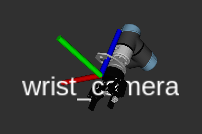
- Positive X points to right of camera.
- Positive Y points up towards the top of the camera.
- Positive Z points to behind the camera.
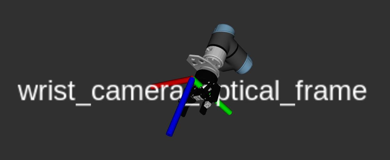
The camera optical frame should be set to the
<camera>position rotated 180 degrees about its x-axis.tipWhen using MuJoCo's interactive viewer, you can quickly obtain the
<camera>and<site>definitions for a scene camera by adjusting your viewpoint and copying the equivalent camera pose using theCopy camerabutton under theRenderingtab on the left hand side of the viewer. You can paste the camera position in your XML description, which will contain a position (pos) and orientation (xyaxes). Be sure to add thename,fovy,mode, andresolution, as shown in the example above. To determine the camera optical frame, multiply the cameraxyaxesorientation by1 1 1 -1 -1 -1and use the same position as the camera.<worldbody>
...
<!-- Add a scene camera -->
<camera
name="scene_camera"
pos="-1.046 1.252 2.019"
fovy="58"
mode="fixed"
resolution="640 480"
xyaxes="-0.607 -0.795 0.000 0.555 -0.424 0.715"
/>
<site
name="scene_camera_optical_frame"
pos="-1.046 1.252 2.019"
xyaxes="-0.607 -0.795 0.000 -0.555 0.424 -0.715"
/>
</worldbody> -
Optionally, update the
render_publish_rateparam in the*ros2_control_macro.xacroused by yourconfig.yamlrobot_description.urdf.noteFor example_robot_ws we will do this in the Overload Configuration for Simulation guide.
  <ros2_control>
    <hardware>
      <plugin>picknik_mujoco_ros/MujocoSystem</plugin>
      ...
      <param name="render_publish_rate">10</param>
    </hardware>
  </ros2_control>
Simulated Lidar Sensor
For example_robot_ws we will skip this step as it does not need a lidar.
-
Add a site for each lidar laser angle using the
<replicate>tag in the MJCF along with a<rangefinder>. Ex:<replicate count="360" sep="-" offset="0 0 0" euler="0.0174533 0 0">
<site name="lidar" size="0.01" pos="-0.075 0.0 0.0" quat="0.0 0.0 0.0 1.0"/>
</replicate>
...
<sensor>
<rangefinder site="lidar" user="0.1 -3.14159 3.14159 0.0174533 0.1 6.0"/>
</sensor> -
Optionally, update the
lidar_publish_rateparam in the*ros2_control_macro.xacroused by yourconfig.yamlrobot_description.urdf.<ros2_control>
<hardware>
<plugin>picknik_mujoco_ros/MujocoSystem</plugin>
...
<param name="lidar_publish_rate">60</param>
</hardware>
</ros2_control>
Optional: Add Scene Geometry
Add lighting, a floor, and additional geometry via <attach> or other means.
There are many assets available in repositories including:
- https://github.com/vikashplus/furniture_sim
- https://github.com/vikashplus/object_sim
- https://github.com/kevinzakka/mujoco_scanned_objects
This will add a basic floor and lighting:
<?xml version="1.0" ?><mujoco model="r6_2f_proto1">
  ...
  <asset>
    <texture
      type="2d"
      name="groundplane"
      builtin="checker"
      mark="edge"
      rgb1="0.2 0.3 0.4"
      rgb2="0.1 0.2 0.3"
      markrgb="0.8 0.8 0.8"
      width="300"
      height="300"
    />
    <material
      name="groundplane"
      texture="groundplane"
      texuniform="true"
      texrepeat="5 5"
      reflectance="0.2"
    />
  </asset>

  <visual>
    <headlight diffuse="0.6 0.6 0.6" ambient="0.1 0.1 0.1" specular="0 0 0" />
    <rgba haze="0.15 0.25 0.35 1" />
    <global azimuth="120" elevation="-20" />
    <map zfar="50" />
  </visual>

  <worldbody>
    <light pos="0 0 2.5" dir="0 0 -1" directional="true" />
    <geom
      name="floor"
      pos="0 0 0"
      size="0 0 0.05"
      type="plane"
      material="groundplane"
    />
  </worldbody>
Troubleshooting
There are additional troubleshooting resources in our Digital Twin Troubleshooting page here.
Your workspace should now look like step9.