Overview
This package contains a Joint Trajectory with Admittance Controller (JTAC), implemented within the ros2_control framework. The JTAC is similar to the ros2_control Joint Trajectory Controller (JTC), with the addition of an optional 'admittance' component that enables executing joint-space trajectories with compliance in Cartesian space. For this, a force/torque sensor (FTS) is needed at the end of the kinematic chain being controlled. Otherwise the controller can still be used, but as a standard joint-trajectory controller without compliance.
Why not use ros2_control JTC + layered admittance?
This same behavior could potentially be achieved with ros2_control JTC and a layered Admittance controller. That approach, however, has a few issues that prevent using it outside of prototype-grade implementations:
- The JTC in
ros2_control allocates memory in the control loop, which makes it unsuitable for real-time systems.
- The Admittance controller in
ros2_control also allocates memory in functions used in real-time loops.
- Controllers in
ros2_control are implemented in a way they depend on other ROS 2 types and messages, which makes them difficult to use outside the ROS ecosystem.
- Having separate layered JTC and Admittance controllers makes it impossible to share the state between them without large architectural changes. Not having a shared state makes it difficult to implement important functionality, such as stopping a trajectory when the force exceeds a threshold, or just resetting the admittance state when a new trajectory is received.
Our approach
Our approach is to implement a new JTC with an embedded admittance component, which we call a Joint Trajectory with Admittance Controller (JTAC). This offers several advantages:
- Having trajectory tracking and admittance in the same controller allows both components to have full access to each others’ state and handle transitions properly (e.g. command preemption).
- Trajectory and admittance parameters can be in the same command message, e.g. run a trajectory with given admittance parameters, as opposed to a command and a separate ROS parameter interface. This enables better error handling and reporting.
- It offers the possibility to update the command message as needed, e.g. different admittance on different trajectory segments, without potentially affecting other controllers.
Design
The JTAC has been designed with the following ideas in mind:
- ROS-agnostic core library +
ros2_control wrapper. This makes it easier to reuse the core in other control frameworks outside ROS if needed.
- The admittance parameters are part of the controller command, as opposed to a separate ROS 2 parameters.
- Real-time safe: no allocations in real-time thread. Validated via memory allocation tests (see malloc_counter.hpp).
- Exit conditions as part of the command, e.g. exit on a maximum deviation threshold from the nominal trajectory, or exit on excessive sensed force.
- All exit conditions should end in a full stop at user-defined decelerations.
- MISRA C++ 23 compliant.
Frames
There are four frames involved in the JTAC computations:
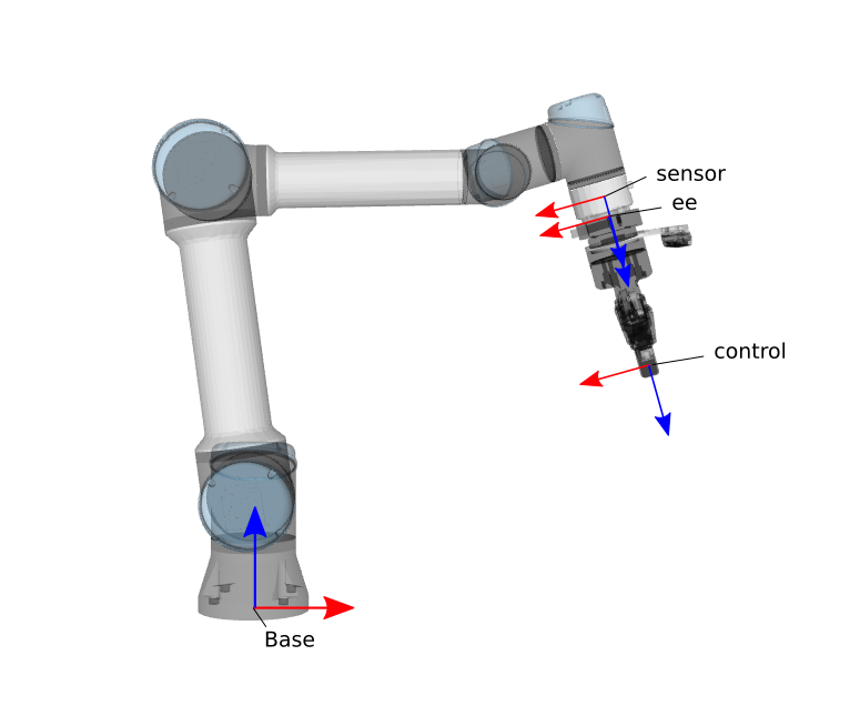
Frames involved in the JTAC
- Base frame: the root of the kinematic chain to be controlled, e.g. the base link of the arm.
- Sensor frame: the frame where the sensed force/torque is given by the FTS.
- End-effector (ee) frame: the tip of the kinematic chain where the end-effector is attached. The end-effector center of gravity will be given with respect to this frame.
- Control frame: the frame that is being controlled, normally a descendant of the end-effector frame, e.g. the tool tip.
Control approach
The controller has a joint-space trajectory tracking component, and an admittance component. In the absence of any force/torque at the end-effector, or if there isn't a force/torque sensor, the controller behaves as a joint trajectory controller, i.e. it tracks a given joint-space trajectory. In the presence of a sensed wrench, the controller deviates from the nominal trajectory according to a spring-mass-damper model, i.e. it deviates as needed to accommodate the force, then converges back to the nominal trajectory when the force/torque disappears:
Spring-mass-damper model
The spring-mass-damper behavior is applied in Cartesian space, and mapped into joint-space via the robot kinematic model. The following image shows the spring-mass-damper model applied in Cartesian coordinates at the robot tip.
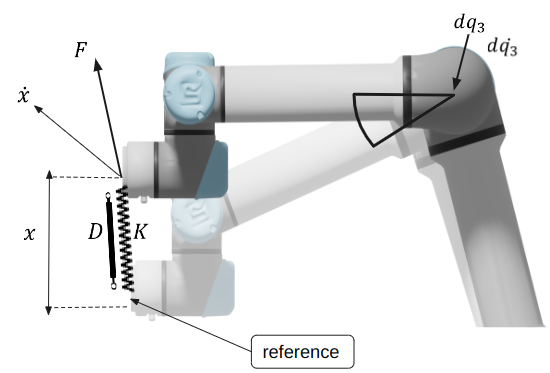
Spring-mass-damper model UR5
The arm is following a trajectory and needs to reach a joint-space reference (semi-transparent UR5). The robot is currently at a different joint-space configuration because a sensed wrench F made it deviate. The controller computes the displacement from the current configuration, in Cartesian space, to the desired one, x. It then applies the spring-mass-damper model with user given mass (M), stiffness (K) and damping (D) parameters, and the sensed wrench F. The output of the model is a Cartesian-space acceleration at which the arm end-effector needs to move. That Cartesian-space acceleration is then transformed into joint-space via inverse differential kinematics, and integrated into new joint-space velocities and accelerations.
Here's a more detailed control diagram:
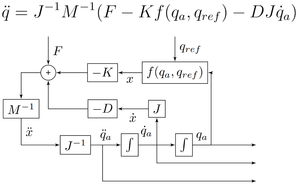
Spring-mass-damper model UR5
Force filtering
The sensed wrench goes through a sequence of steps before it gets used by the controller:
- A second-order Butterworth filter is first applied to the raw input, to filter out high-frequency noise.
- A configurable deadband is applied to filter out values close to zero, which helps with control stability.
- The wrench introduced by the end-effector weight under gravity is estimated and subtracted from the filtered wrench before feeding it to the controller.
The behavior of these filters can be configured via the runtime parameters ft_cutoff_frequency_ratio, ft_force_deadband, ft_torque_deadband and gravity_vector (see the Parameter interface section below).
ROS Interface
The JTAC is exposed to the ROS 2 ecosystem as a ros2_control plugin with name moveit_pro_controllers/JointTrajectoryAdmittanceController. It exposes three ROS 2 interfaces:
- Command action interface, used to send commands to the controller, e.g. a trajectory to be executed.
- Parameter interface, used to configure the controller from configs, or at runtime.
- State topic interface, used by the controller to communicate internal state to clients.
Command action interface
The controller command interface is exposed as a ROS 2 Action. The action message and its documentation is included in moveit_pro_controllers/FollowJointTrajectoryWithAdmittance.action.
Unlike the JTC in ros2_control, the JTAC won't report the command as finished until the robot is fully stopped. If, for instance, an error happens during trajectory execution (e.g. excessive force), the controller will plan and execute a minimum-time stop trajectory before returning control to the caller.
State topic interface
The controller state is published as a control_msgs/JointTrajectoryControllerState message, and includes the reference state, the actual state and the current error.
How to make the controller available
To make the JTAC available in your configs, add and adapt the following snippet to your ros2_control.yaml config file:
controller_manager:
ros__parameters:
joint_trajectory_admittance_controller:
type: moveit_pro_controllers/JointTrajectoryAdmittanceController
# UR5 example.
joint_trajectory_admittance_controller:
ros__parameters:
joints:
- shoulder_pan_joint
- shoulder_lift_joint
- elbow_joint
- wrist_1_joint
- wrist_2_joint
- wrist_3_joint
base_frame: base_link
sensor_frame: tool0
ee_frame: grasp_link
ft_sensor_name: tcp_fts_sensor
stop_accelerations:
- 100.0
- 100.0
- 100.0
- 100.0
- 100.0
- 100.0
Parameter reference
Here's the list of all the parameters that can be configured, with their descriptions and default values:
joint_trajectory_admittance_controller:
joints: {
type: string_array,
description: "Specifies which joints will be used by the controller.",
read_only: true
}
base_frame: {
type: string,
default_value: "",
description: "Specifies the base link of the kinematic chain. Must exist in the robot description."
}
sensor_frame: {
type: string,
default_value: "",
description: "Specifies the frame/link name of the force torque sensor. Must exist in the robot description."
}
ee_frame: {
type: string,
default_value: "",
description: "Specifies the frame/link name of the end-effector frame. Must exist in the robot description."
}
ft_sensor_name: {
type: string,
default_value: "",
description: "Specifies the name of the force torque sensor in the robot description which will be used in the admittance calculation. If empty, the controller will run without admittance."
}
ft_cutoff_frequency_ratio: {
type: double,
default_value: 1.0,
description: "Specifies the cutoff frequency ratio for the FTS filter. Valid values range from 0 to 1, where 1 is the sampling frequency.",
validation: {
bounds<>: [0.0, 1.0]
}
}
ft_force_deadband: {
type: double,
default_value: 0.0,
description: "Specifies the deadband threshold for the force measurements (N).",
validation: {
gt_eq<>: 0.0
}
}
ft_torque_deadband: {
type: double,
default_value: 0.0,
description: "Specifies the deadband threshold for the torque measurements (Nm).",
validation: {
gt_eq<>: 0.0
}
}
state_publish_rate: {
type: int,
default_value: 50,
description: "Rate in Hz at which the controller will publish the state.",
validation: {
gt<>: 0
}
}
jacobian_damping: {
type: double,
default_value: 0.01,
description: "Specifies the damping coefficient for the Jacobian damped least-squares inverse.",
validation: {
gt<>: 0.0
}
}
gravity_vector: {
type: double_array,
default_value: [0.0, 0.0, -9.8],
description: "Gravity vector in the URDF root frame (world).",
validation: {
fixed_size<>: 3
}
}
default_path_tolerance: {
type: double,
default_value: 0.05,
description: "Default maximum joint-space deviation accepted along the trajectory.",
validation: {
gt<>: 0.0
}
}
default_goal_tolerance: {
type: double,
default_value: 0.05,
description: "Default maximum joint-space deviation accepted at the trajectory end-point.",
validation: {
gt<>: 0.0
}
}
default_absolute_force_torque_threshold: {
type: double_array,
default_value: [45.0, 45.0, 45.0, 10.0, 10.0, 10.0],
description: "Default maximum absolute force torque readings allowed from the force torque sensor along each Cartesian space axis. If exceeded, execution will abort.",
validation: {
lower_element_bounds<>: [0.0],
fixed_size<>: 6
}
}
stop_accelerations: {
type: double_array,
description: "Accelerations to be used for stopping a trajectory, one element per robot joint.",
validation: {
lower_element_bounds<>: 0.0
}
}
Relevant headers