4. Motion Planning
🕒 Duration: ~2 hours
💪 Level: Intermediate
Tutorial Overview
This tutorial introduces the powerful motion planning capabilities of MoveIt Pro, combining navigation, perception, and whole-body planning into a unified workflow. Set in the hangar_sim environment, you’ll learn the types of motion planning MoveIt Pro supports:
- Joint-space planning: Planning the arm (and optionally the base) to move to a specific joint configuration, avoiding obstacles.
- Cartesian planning: Planning the arm (and optionally the base) to move along a path in Cartesian space. This includes generating automated surface coverage paths.
- Task planning: Planning complex tasks that involve multiple steps, such as pick-and-place operations, using the MoveIt Task Constructor (MTC).
- Mobile base navigation: Planning the mobile base to move to a specific location in the environment, avoiding obstacles, while the arm is static.
We'll finish with a complex example of an ML-based pick-and-place task combining all the building blocks learned so far.
Pre-reqs
You should have already installed MoveIt Pro. We will assume you have already completed Tutorial 1 and know how to build Behavior Trees.
For this tutorial it's important to understand the distinction between planning and control:
- Planning refers to the process of computing a valid path or trajectory for the robot to follow, given its current state and the desired target. This is typically done using motion planners, which take into account the planning scene and the robot's kinematics.
- Control refers to the process of executing the planned trajectory on the robot's hardware.
The output of the planning process is typically a joint-space trajectory, which is the input to the control component. Collision checking is normally done during the planning phase, to ensure that the planned trajectory does not collide with any obstacles in the planning scene, since controllers typically do not perform collision checking.
Start MoveIt Pro
Launch the application using:
moveit_pro run -c hangar_sim
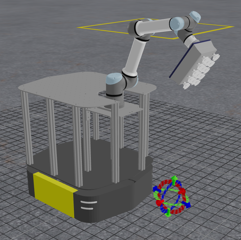
The hangar_sim robot config launches a virtual environment representing an airplane hangar with a mobile manipulator. The robot has a mobile base, a robotic arm, and integrated sensors.
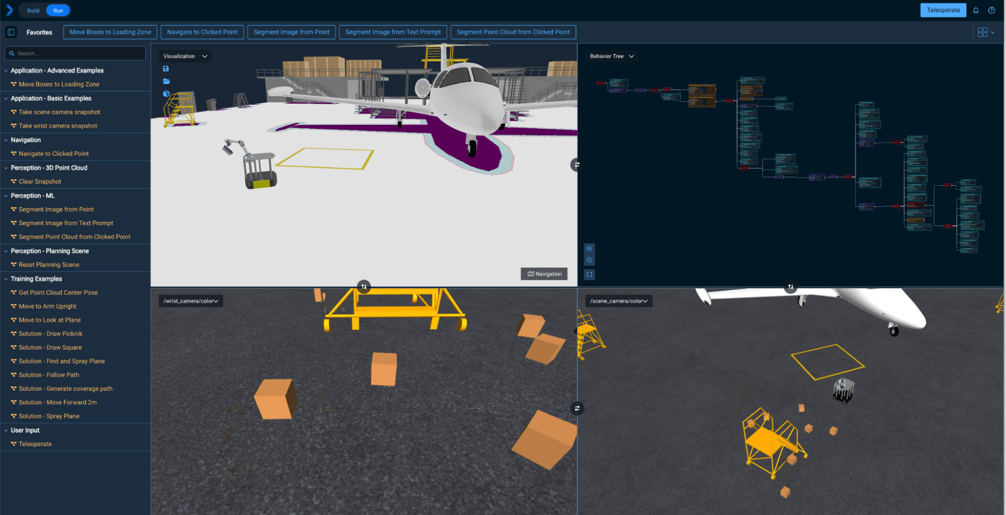
By default this hangar_sim robot config shows the Navigation cost map, though you can toggle this on and off. We'll learn more about this towards the end of the tutorial.
Direct Joint-Space Motion (without considering obstacles)
Let's start with a simple Objective that moves the robot arm to a predefined joint-space waypoint by creating a direct point-to-point joint-space trajectory, without any motion planning involved. It will check for collisions but not plan around collision objects.
A joint-space waypoint, which is also called a joint state, represents the values of the robot's actuators, including their positions, velocities, and efforts. It is used to describe the robot's configuration in joint space. In MoveIt Pro, joint states are represented by the moveit_studio_agent_msgs::RobotJointState message type, which can contain multiple joint states for different robot components (e.g., arm, base).
Pre-defined waypoints in MoveIt Pro can be loaded into a RobotJointState type by using the RetrieveWaypoint Behavior.
A joint-space trajectory is a sequence of joint states that defines how the robot's actuators should move over time. It is typically represented as a trajectory_msgs::JointTrajectory message, which includes the joint names, positions, velocities, and accelerations for each point in the trajectory.
Let's try it out:
- Create a new Objective called "Execute joint-space trajectory".
- As always, remove the default Behavior
AlwaysSuccess - Add a
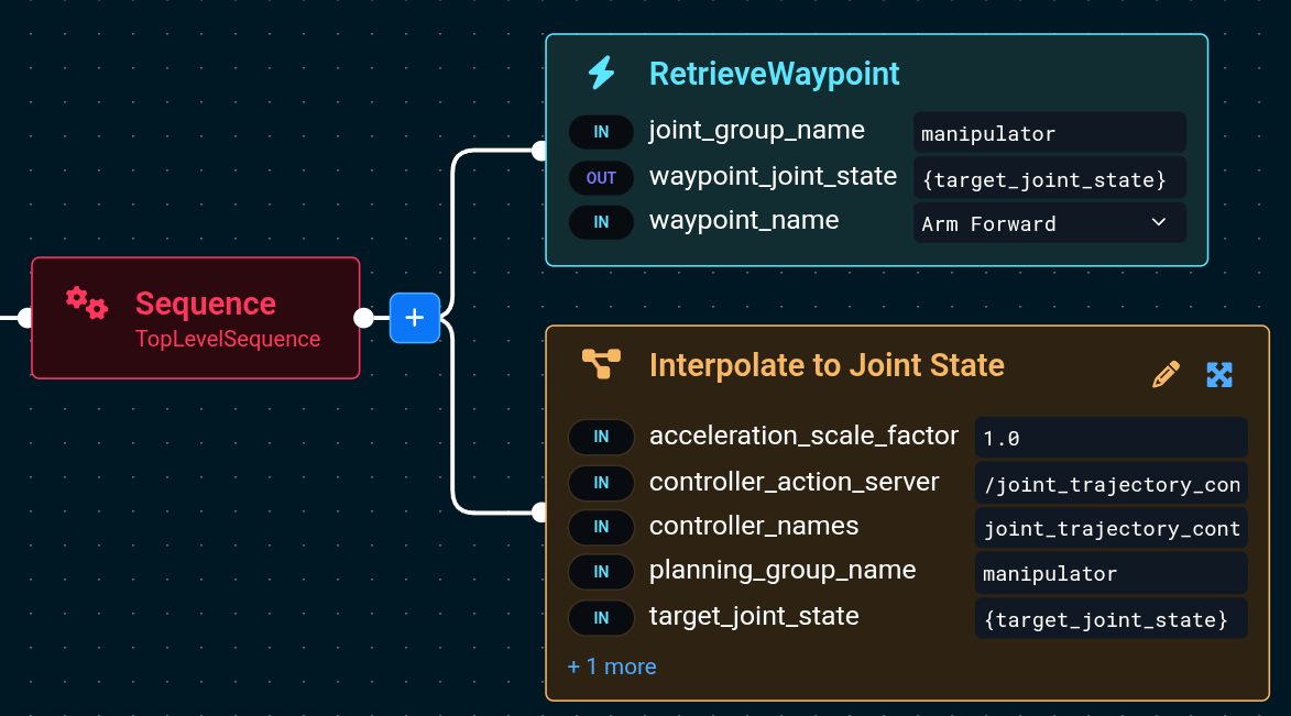
RetrieveWaypointBehavior to load the joint state based on the named waypoint - For the
joint_group_namecopy in the planning group calledmanipulator, which includes both the arm and AMR mobile base. - Select any named waypoint in the
waypoint_namedrop down, for exampleArm Forward - Add a Subtree Objective called
Interpolate to Joint Statethat will take the loaded joint state and send it to the robot for execution.
Your Behavior Tree should look like the following:
Next, Run this Objective.
It will retrieve the waypoint called Arm Forward and move the robot arm to that configuration.
Let's explore the Interpolate to Joint State subtree:
-
Go back to Edit your newly created Objective
-
Click the Expand all button in the bottom left of the Behavior Tree editor.

-
Also click the Fit to View button in the same set of icons.
-
Notice the main Behaviors involved in the Objective:
-
GetCurrentPlanningSceneretrieves the robot's current understanding of its environment, which is used to extract the current robot joint state later, withGetRobotJointState. -
GeneratePointToPointTrajectorycreates a joint-space trajectory from the 'start' joint state to the 'target' joint state. -
SwitchControllerensures the correct real-time controller methodology is running, in our case the basic "joint_trajectory_controller" -
ValidateTrajectorychecks if the generated trajectory does not collide with any obstacles in the planning scene.noteThis Objective won't perform any motion planning around obstacles; it will move the robot arm directly to the specified waypoint. This is useful for simple tasks where you know the exact joint positions you want to move to, and the direct path is feasible. We still check for collisions with the
ValidateTrajectoryBehavior - the Objective will detect if the trajectory is going to collide - however it will not try to find a different path if it does. -
ExecuteFollowJointTrajectorysends the trajectory on the robot's hardware to be run.
-
-
Explore the input ports of the
GeneratePointToPointTrajectoryBehavior. Read the built-in documentation for the node to understand how you can set the speed of the trajectory, etc: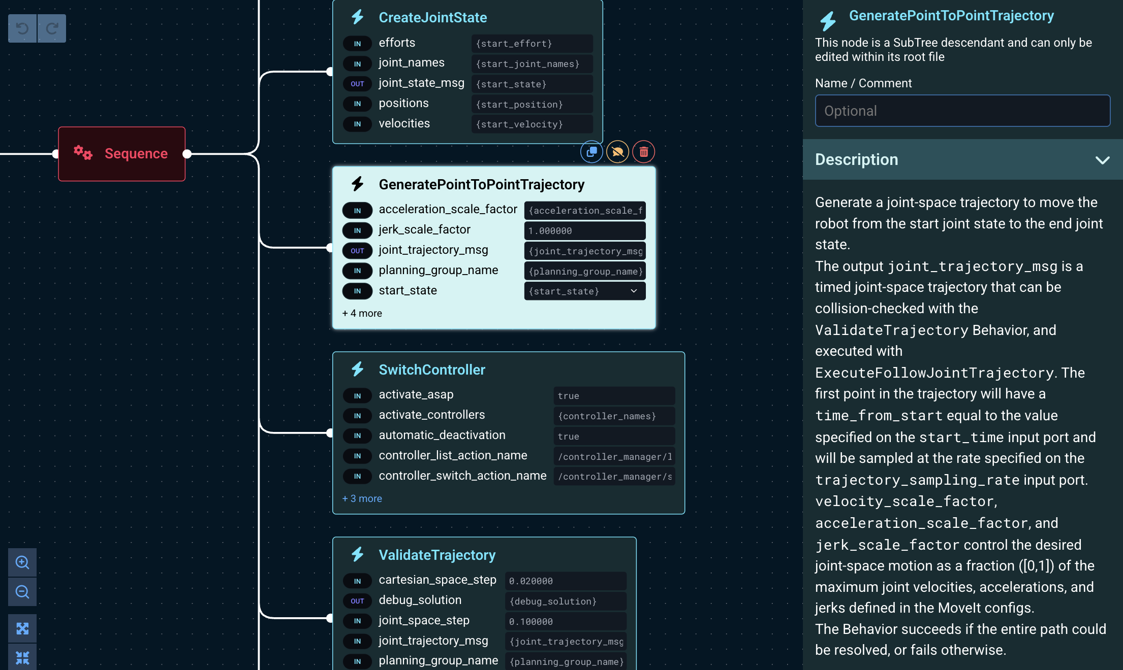
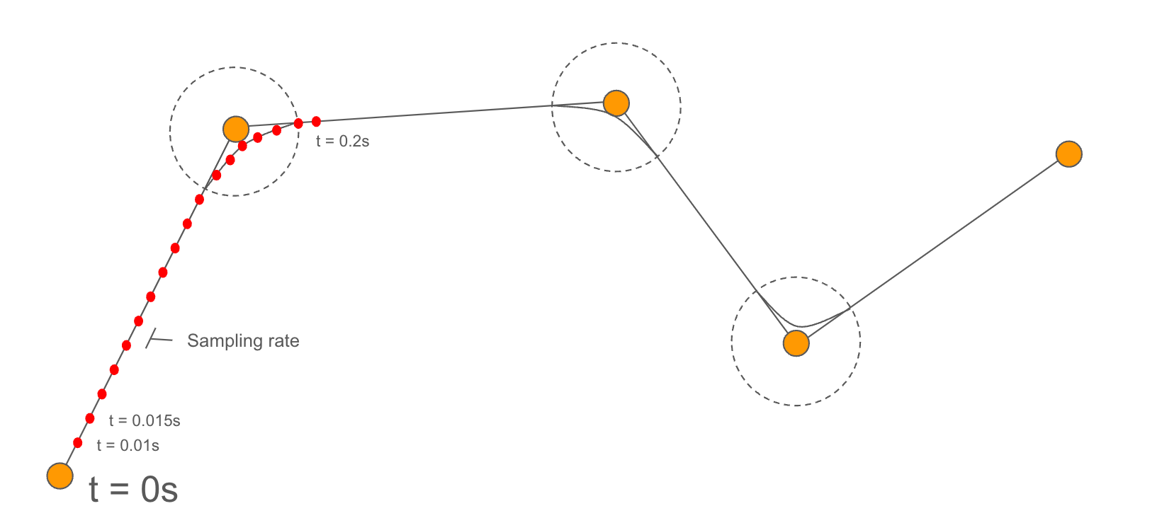
Motion planners typically take as input Cartesian-space or joint-space targets, and output joint-space trajectories, which can be executed by the robot's controllers. Trajectories are generated at a given sampling rate, which is the frequency at which the controller expects to receive new trajectory points. Points in the trajectory (also called setpoints) are evenly spaced in time at the specified sampling rate.
Global Freespace Planning (around obstacles)
In this section we will learn how to plan trajectories around obstacles in joint-space.
Joint-space planning to a joint goal
In this section we will learn how to plan joint-space paths for the robot arm, which at its core uses the PlanToJointGoal Behavior. PlanToJointGoal can plan a path to a specific joint configuration, avoiding obstacles in the planning scene.
-
Find and Edit the existing Objective called
Move to Arm Upright. -
Click Expand All to see the following. Notice the two main subtrees in the Objective:
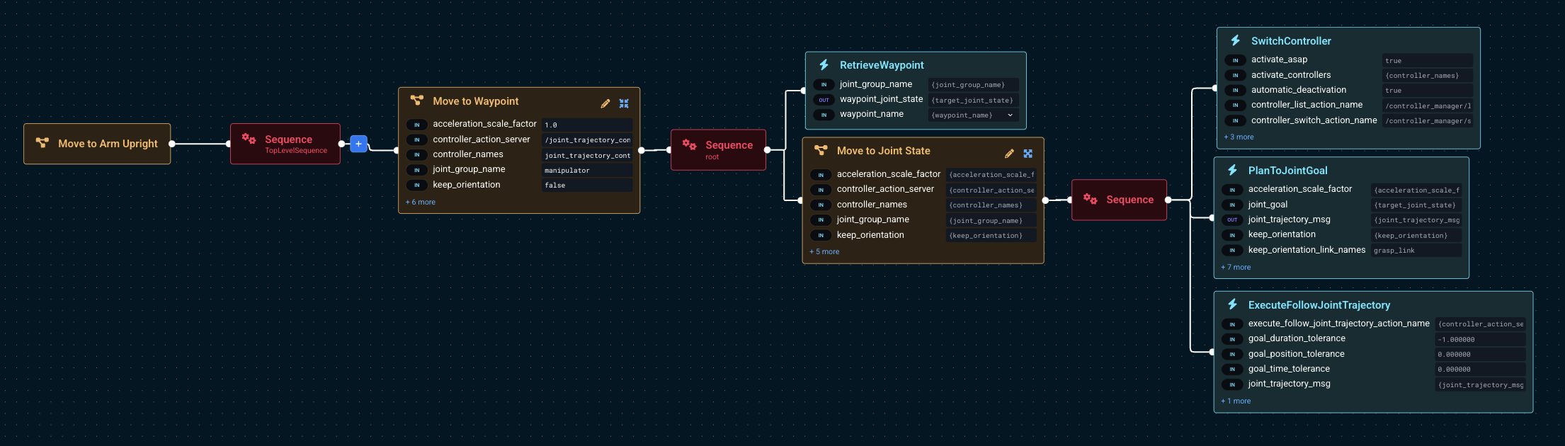
-
Take your time to explore the contents of the
Move to Joint StateSubtree, which moves the robot arm to a specific joint configuration, using motion planning around obstacles.SwitchController: Changes the robot controller to thejoint_trajectory_controller, which is used to execute joint-space trajectories.PlanToJointGoal: Generates a joint-space trajectory to the target joint configuration, avoiding obstacles in the planning scene.ExecuteFollowJointTrajectory: Sends the planned joint-space trajectory on the robot's hardware to initiate action.
noteUnlike the
Interpolate to Joint Stateexample described previously, this Objective will perform motion planning around obstacles, which includes collision checking. Therefore it is not necessary to validate the trajectory again with theValidateTrajectoryBehavior, as it is done already as part of the planning process. That's why the trajectory can be executed directly with theExecuteFollowJointTrajectoryBehavior. -
Click on the
PlanToJointGoalBehavior to expand its parameters sidebar.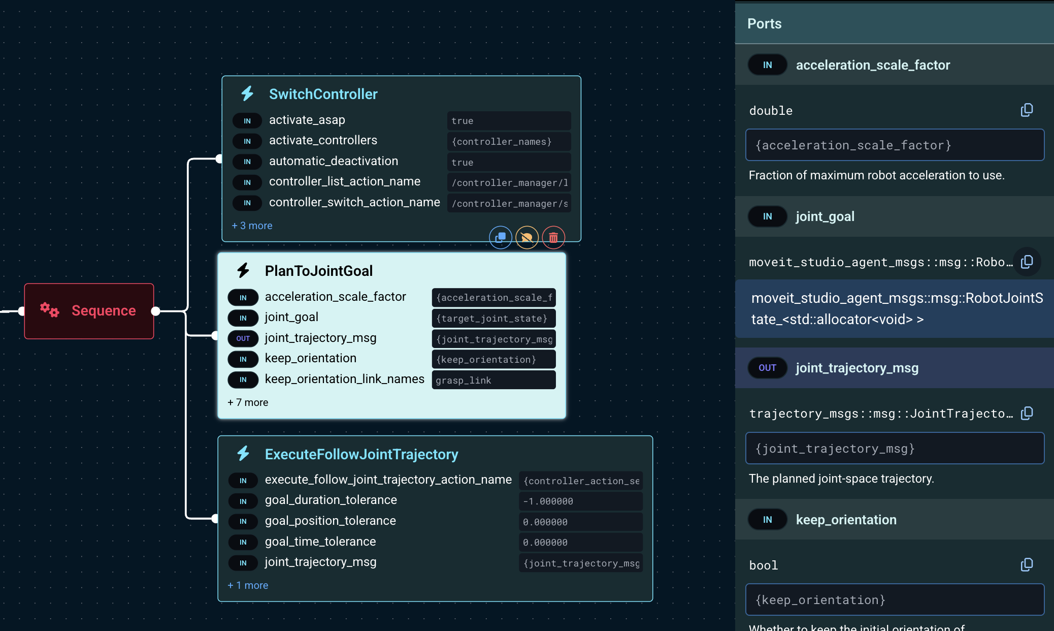
-
Take some time to explore the input ports of
PlanToJointGoaland its documentation, specifically:joint_goal: The target joint configuration to plan to.keep_orientationand other related parameters: These control how the planner handles the end effector orientation during the planning process.velocity_scale_factorandacceleration_scale_factor: These control the speed and acceleration of the planned trajectory, relative to the robot's maximum speed and acceleration.seedandmax_iterations: These control the random seed and maximum number of iterations for the planner, which can be useful for exploring different planning solutions or dedicating more time to solving the planning problem.
The trajectory execution speed is set at planning time via the velocity_scaling_parameter and can't be adjusted while it's being executed. However, this will soon be possible, as the feature is planned for version 8.6.
Moving in joint-space to a 3D pose
A common use case is to move the robot end effector to a specific 3D pose in space while avoiding obstacles.
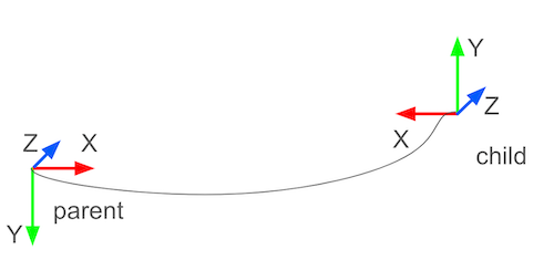
A pose is a representation of an object's position and orientation in space. It is typically represented as a geometry_msgs::PoseStamped message, which includes a position (x, y, z) and orientation (quaternion). Poses are frequently used to define the target positions for the robot's end effector during motion planning, or the location of a robot link in the environment.
A geometry_msgs::PoseStamped type contains the pose of a ‘child’ frame in the ‘parent’ coordinates.
Moving in "end effector" space requires computing the Inverse Kinematics (IK) for the target pose, to determine the joint configuration that achieves that pose, and moving to that joint configuration.
Inverse Kinematics (IK) is the process of calculating the joint angles or actuator positions needed to place the end effector (like a gripper or tool) at a desired position and orientation in space. Unlike Forward Kinematics, which tells you where the end effector will be given specific joint angles, IK works in reverse: it starts with the target location and figures out how to move the robot’s joints to get there.
The ComputeInverseKinematics Behavior can be used to compute the IK for a given pose, and then the PlanToJointGoal Behavior can be used to plan a trajectory to that joint configuration.
-
Open the Objective
Compute IK, Plan and Move -
Examine its Behavior Tree structure. These are the main Behaviors involved:
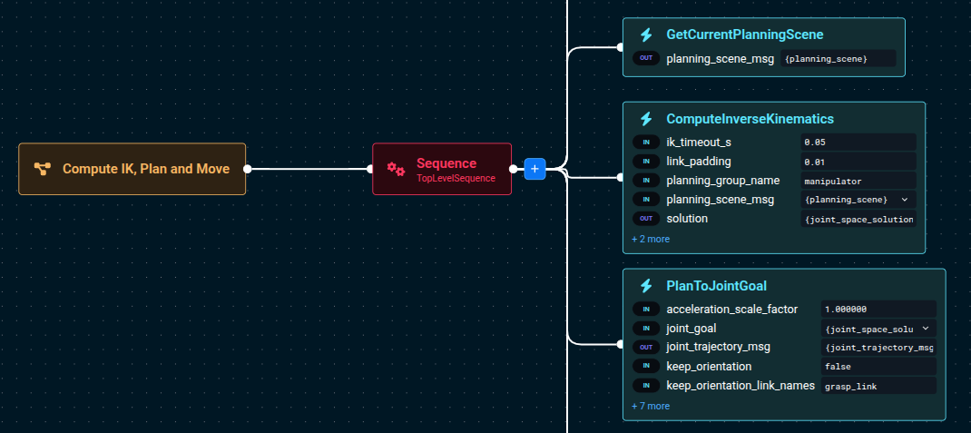
-
Next, run this Objective to see it move its end effector
0.3mforward, each time you run it.
ComputeInverseKinematics takes a vector of target poses instead of a single pose, because it can compute IK for multiple links simultaneously (e.g. multi-arm systems).
Therefore you'll need to put the target pose in a vector, using AddPoseStampedToVector.
Cartesian planning
Cartesian planning creates a trajectory where the robot’s end effector follows a precise series of poses in space, often along a straight line or curve. This is useful for painting, welding, spraying, drawing, or scanning—where the tool must stay in contact with or aligned relative to a surface.
A Cartesian path is just a sequence of poses in Cartesian, or end effector, space.
Common characteristics of Cartesian-space planning:
- Path is defined in Cartesian (X, Y, Z + orientation) space.
- Planner ensures smooth transitions using waypoints.
- A drawback is that it is sensitive to collisions and IK feasibility.
This is in contrast to freespace planning, which plans a trajectory from a start to goal configuration without specific constraints on the path itself. Freespace planning solves for a valid, collision-free path in joint space, but it may produce curved, non-intuitive motions.
MoveIt Pro supports combining free space planning and Cartesian planning, and allows blending them using composite Behaviors, depending on your task’s complexity.
Cartesian plan to a single pose
Let’s start learning about Cartesian planning by moving to a single 3D pose. Later we will plan through a series of points.
We previously introduced the Compute IK, Plan and Move example as a way to move to a target 3D Pose.
This example is similar, but it plans and moves in Cartesian-space, instead of joint-space.
The robot end-effector will be constrained to move in a straight line to the target pose.
Let’s create a simple application that moves the robot forward 0.2 meters, in straight line.
-
Create a new Objective called
Move Forward 0.2m -
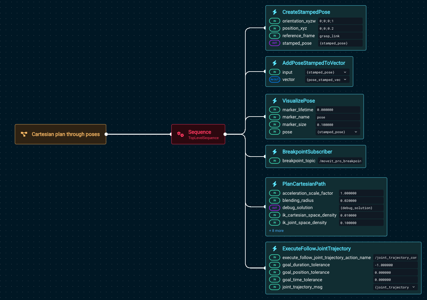
Add the following Behaviors:
- Behavior:
CreateStampedPose- orientation_xyzw =
0;0;0;1 - positions_xyz =
0;0;0.2 - reference_frame =
grasp_link
- orientation_xyzw =
- Behavior:
AddPoseStampedToVector- input =
{stamped_pose}
- input =
- Behavior:
VisualizePose - Behavior:
BreakpointSubscriber - Behavior:
PlanCartesianPath - Behavior:
ExecuteFollowJointTrajectory
- Behavior:
-
Your Behavior Tree should look like this:
-
Take a moment to click on
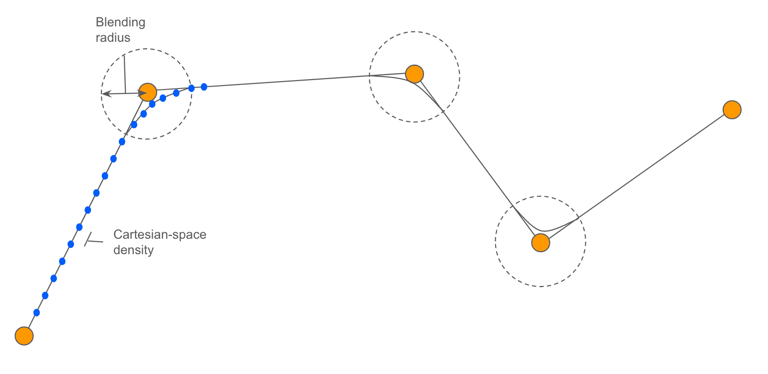
PlanCartesianPathand explore its many parameters that can be tuned.Understanding PlanCartesianPath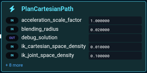
-
The blending radius smooths out the motion between straight lines.
-
The Cartesian-space density is the distance between waypoints at which the Inverse Kinematics are computed (defaults should work well for most applications)
-
-
Before running, we recommend you get the robot in a good position by running the Objective
Move to Arm Upright, which is a shortcut to move to a waypoint. -
Now run
Cartesian plan through poses -
You should see it pause with the visualized pose:
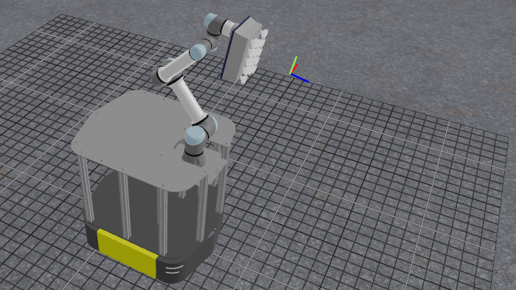
-
Press the Resume button at the top right to continue its operation.
This pattern of creating a pose, visualizing it with VisualizePose, and moving towards it is a common pattern in debugging robot Behaviors in MoveIt Pro.
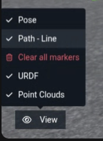
You can Clear all markers between steps to make visualizing things easier.
Cartesian plan to multiple poses
To plan a path of multiple poses, we can create the poses and add them to the path vector by repeating the CreateStampedPose and AddPoseStampedToVector Behaviors.
To see an example without having to build it yourself, let’s explore an Objective that draws a square.
-
Run
Move to Look at Plane -
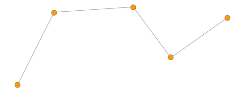
Next, run
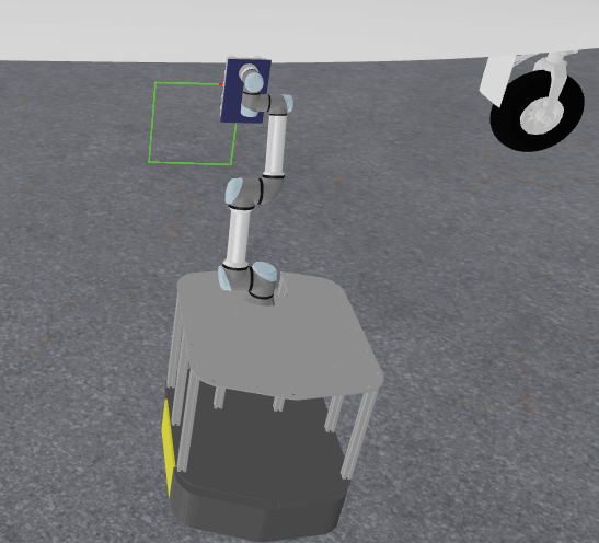
Cartesian Plan Simple Squareand approve the trajectory. -
The robot should produce this result:
 note
noteThe key difference between this example and the previous is that the Cartesian planner is constraining both the end effector position and orientation, by setting the
PlanCartesianPathparameter toposition_only: false. -
Edit the Objective and change the
PlanCartesianPath's parameterposition_onlytotrue.
-
Re-run the Objective and note how the end effector executes the path without staying normal to the plane of the square.
Loading Multi-Pose Paths from File
You can load more complex geometries from file using LoadPoseStampedVectorFromYaml, rather than having to hard-code each pose with Behavior Tree nodes. In this example we load a path from a file called picknik.yaml.

-
Find and run the Objective
Cartesian Draw Geometry From File -
You should see the robot draw the following:
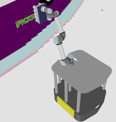
-
Review the Behavior Tree, which should look like this:
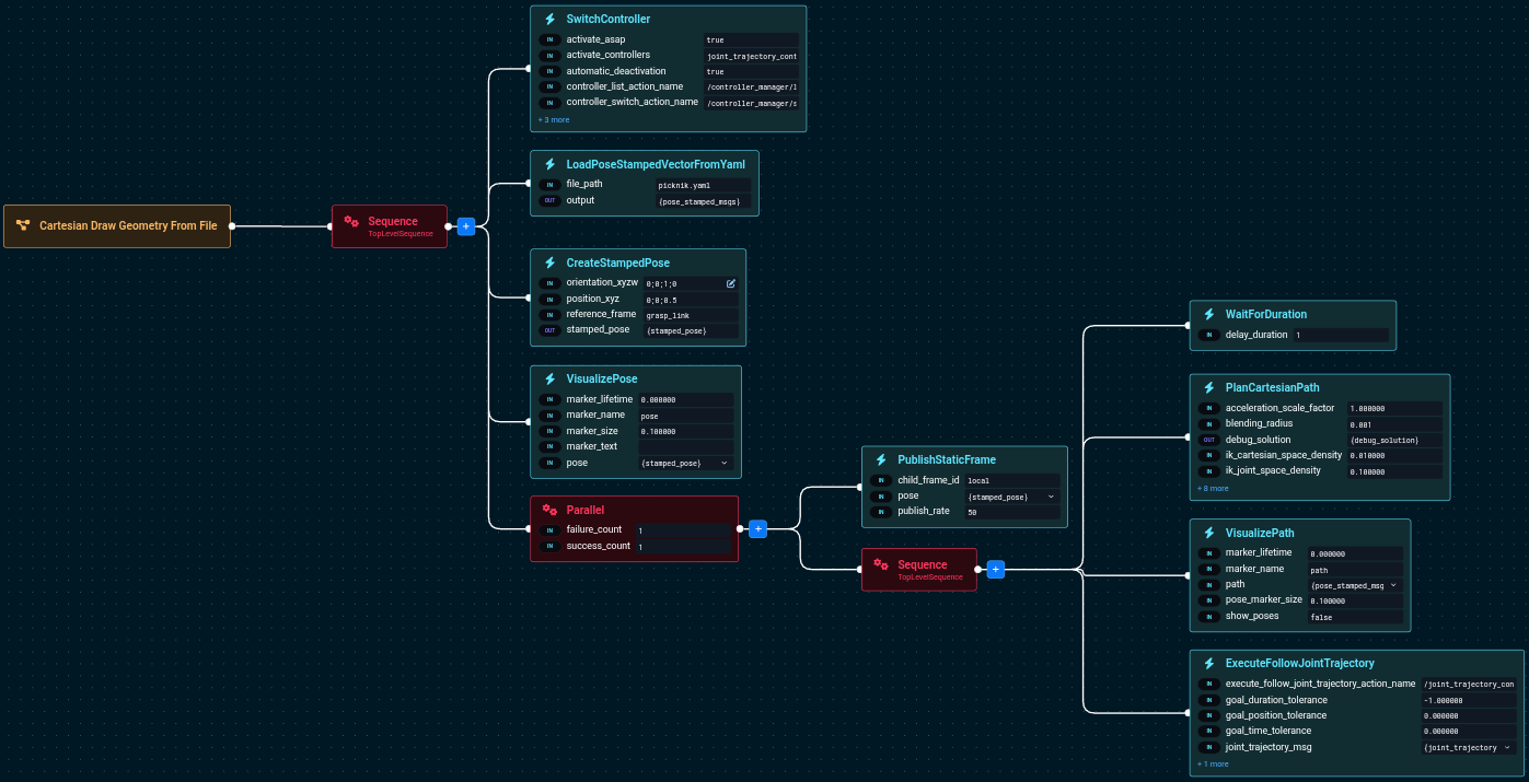
In this Objective we also use the ROS transform library TF to publish a static TF using PublishStaticFrame in the local frame.
Coverage Path Planning
Coverage paths are used in a variety of applications including painting, spraying, sanding, smoothing, or inspecting an area. In this section we will explore how to auto-generate coverage paths for a simple rectangle. More complex coverage paths over contoured surfaces are also possible.
In MoveIt Pro there is a Behavior called GenerateCoveragePath used to create these paths. You can specify the area to cover by providing:
- An origin (the bottom-right corner).
- The width
- The height
The following diagram explains this convention:
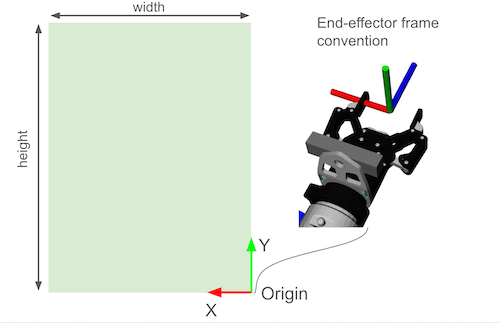
A lawn-mower path is automatically generated, with a given distance between strides.
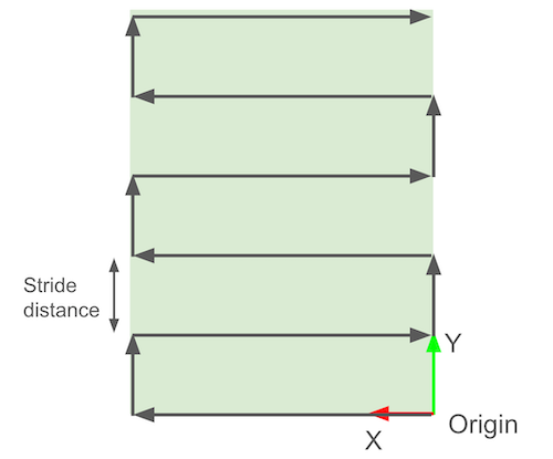
-
Find and run the Objective called
Generate Grid Pattern on Airplane. -
You should see it plan this:
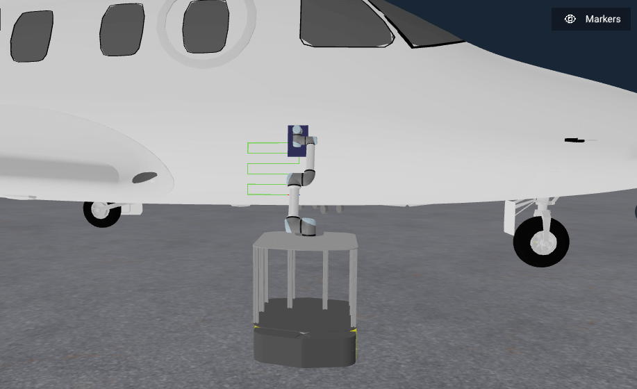
Seems like a small path, right? Let’s modify this Objective:
-
Open this Objective's Behavior Tree for editing
-
Find the Behavior called
GenerateCoveragePathand open up the parameters sidepanel.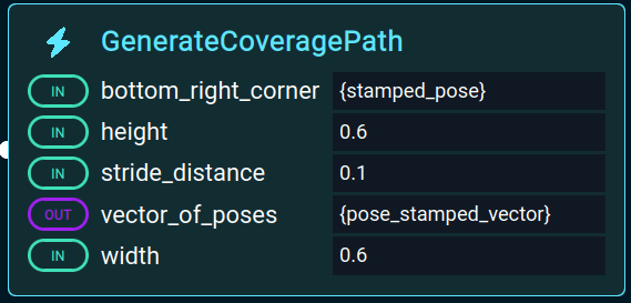
-
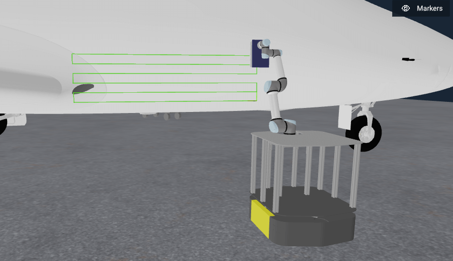
Change the
widthto2.0. -
Re-run the Objective, you should now see a much more impressive path:
-
Try adjusting other settings and see how that affects the coverage path.
Scan & Plan Workflow
Next we bring together all the pieces by combining perception with the Cartesian planning we’ve covered above. In this example the robot scans the side of the airplane before generating the motion plan.
-
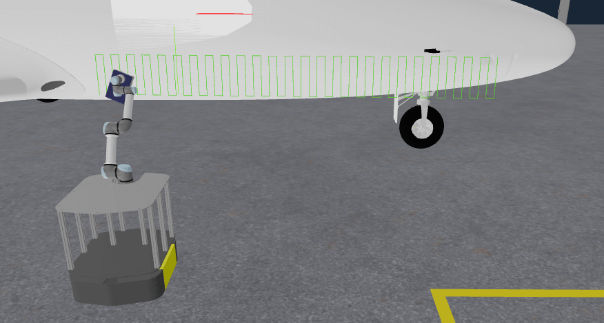
Find and run the Objective
Find and Spray Plane. You should see: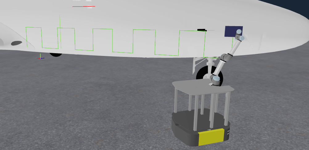
The key difference in this example from the previous section is that we use a pre-built subtree called Get Point Cloud Center Pose. It returns the pose of the plane of the airplane sidebody:
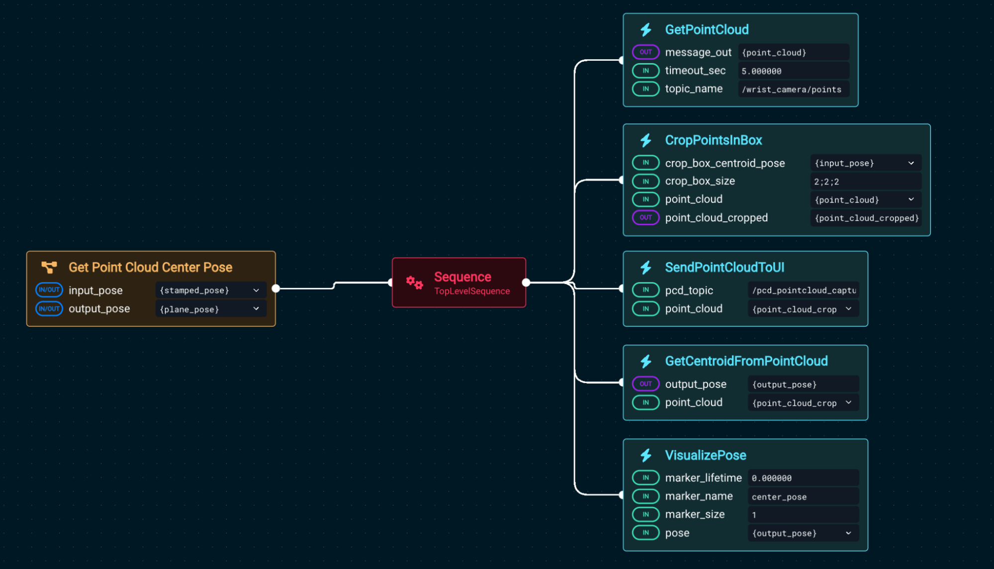
Using that center point, we generate the Cartesian plan. Let’s modify Find and Spray Plane to have a more dense scanning pattern.
-
Edit the Objective
Find and Spray Planeagain. -
Find the Behavior
GenerateCoveragePathand open the parameter sidepanel -
Change the parameter
stride_distanceto0.1. -
Run the Objective. You might notice the motion planner takes longer to compute the new path.
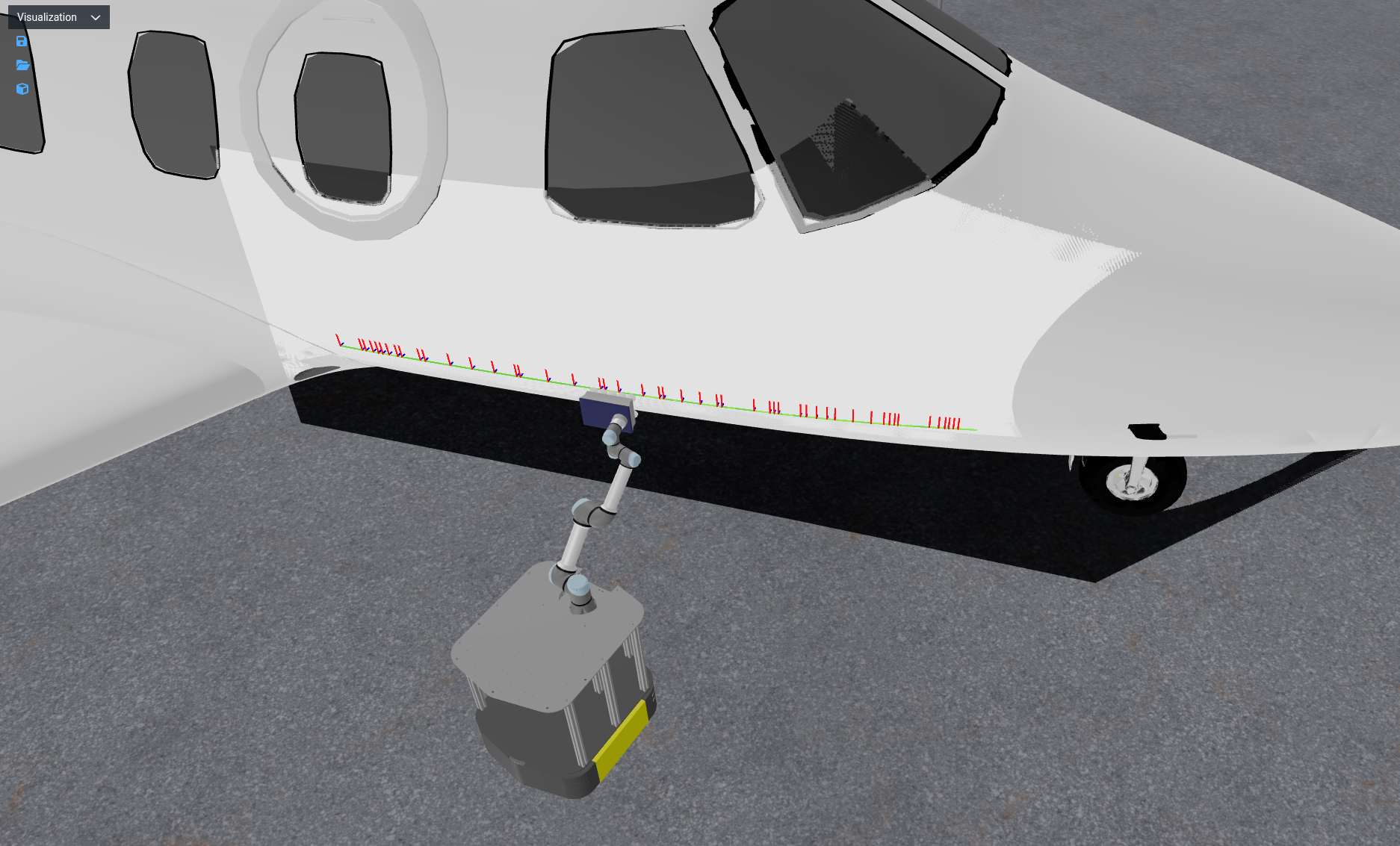
-
You should then see the following path generated:
Planning paths along a surface
You may be asking if it is possible to generate paths along a surface, such as the side of the airplane, rather than just a flat plane. The answer is yes, but it requires more advanced Behaviors.
-
Find and run the Objective
Plan Path Along Surface. -
You should see the robot moving to a waypoint on the side of the airplane, and then generating and executing a path along the surface.
-
Open this Objective's Behavior Tree for editing
-
Notice the main differences from the previous examples:
- The
GetContourFromPointCloudSliceBehavior is used to get a contour of the airplane side, given a point cloud, and a 'slice frame'. - The input point cloud comes from the robot wrist camera, and is filtered to only include points in the region of interest, via
CropPointsInBox. - The start and end points of the path segment are defined by the
contour_crop_angle_startandcontour_crop_angle_spanparameters of theGetContourFromPointCloudSliceBehavior. Feel free to spend some time experimenting with these parameters to see how they affect the path generated. PlanCartesianPathis used, as in the previous examples, to plan the trajectory along the given segment.
- The
These steps can be sequenced together to create more complex coverage paths along surfaces, depending on the application.
Task planning (MTC)
MoveIt Pro provides advanced capabilities for planning complex tasks through the use of the MoveIt Task Constructor (MTC). MTC enables you to break down complex planning tasks into multiple interdependent steps for use by motion planners. It can be used to plan a solution to multi-stage problems.
MoveIt Pro provides a library of Behaviors to make using MTC easier. They provide a simplified way to create, plan, and execute MTC tasks. You can:
- Use Behaviors to set up and extend the task with common building blocks.
- Choose from a variety of building blocks.
- Reuse components of existing tasks much easier than writing low-level C++.
For a simple example of an MTC Objective:
-
Find and view the
Move to PoseObjective -
You will see several MTC Behaviors that move the end effector pose to the target input pose.
infoYou will notice this is yet another way to move the robot end effector to a target pose, similar to the
Compute IK, Plan and MoveandMove Forward 2mexamples we saw earlier. In this case, the planning problem is set up as a more complex search task, where multiple IK solutions will be attempted to find a valid solution that avoids obstacles in the planning scene.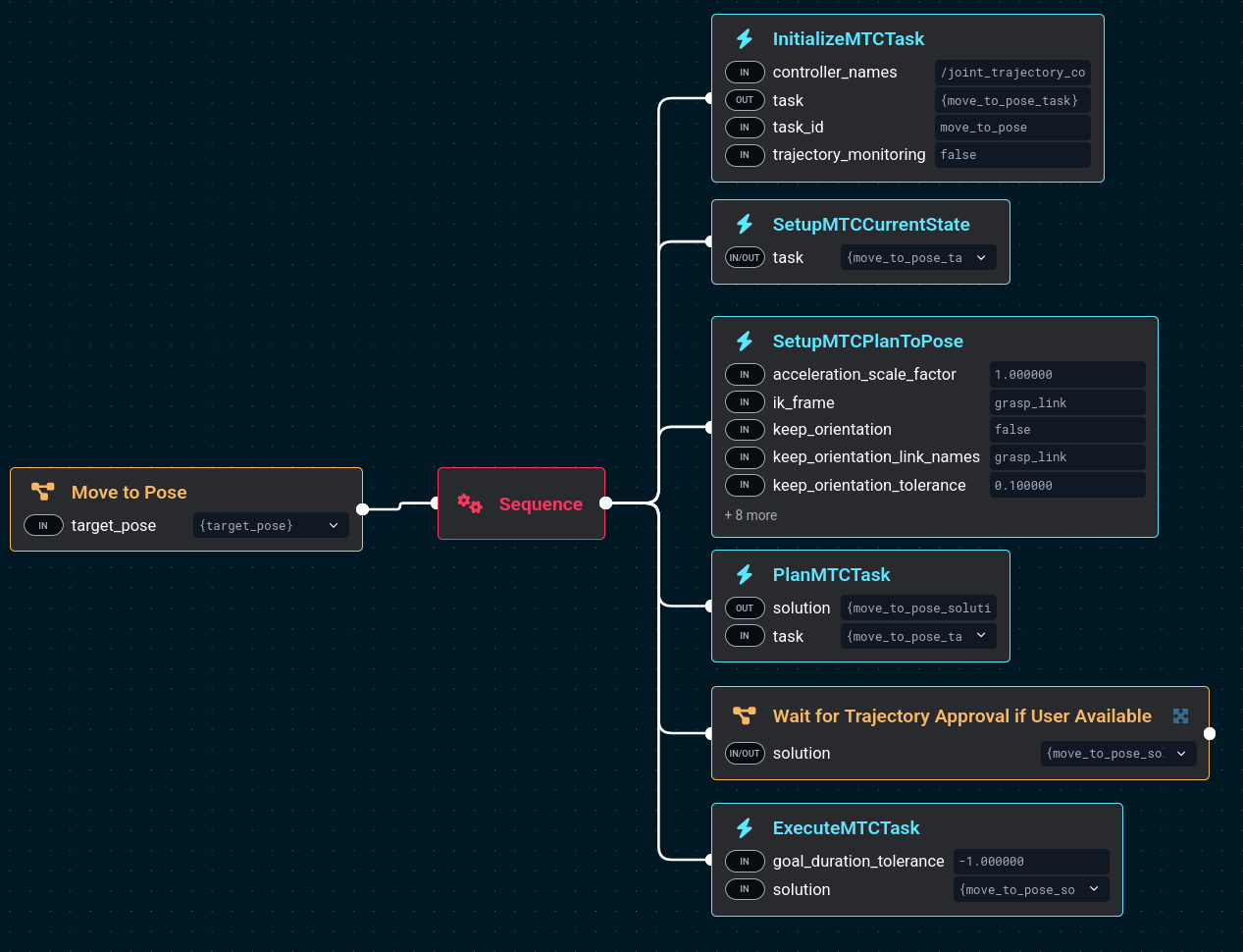
-
Edit the Objective
-
In the sidebar, search for the keyword "MTC" to see all the MTC Behaviors available in MoveIt Pro.
infoThere are many built-in MTC Behaviors, and you will typically use a common structure to build an MTC Objective similar to what you see in
Move to Pose:-
InitializeMTCTaskcreates a task object and initializes the common global properties like trajectory execution info. The task object is then stored on the blackboard to be modified by following Behaviors. -
SetupMTCCurrentStatetakes the created task and sets up a generator stage corresponding to the current state as the task's start state. -
SetupMTCxxxhere you can chain a number of MTC behaviors and stages together to create the desired behavior of your custom Objective.Move to Poseuses theSetupMTCPlanToPosebehavior, which contains several MTC stages. -
PlanMTCTaskcalls the plan() function of the given MTC task and stores the solution to the blackboard. -
ExecuteMTCTaskreads an MTC solution from the blackboard and executes it.
Overall MTC is a complex topic that we do not cover in-depth in these getting started tutorials. For a hands-on example, see the Task Constructor how-to guide.
-
Task Constructor Debugging
In this section we will explore how to introspect failed MTC tasks.
We first need to trigger an MTC failure - to do this we will use teleoperation.
-
Click on the Teleoperation button at the top right
-
Select the IMarker mode
-
Move the virtual marker arrows so that the robot end effector will collide with the floor, similar to shown in the picture:
-
You should see a popup message that
PlanMTCTaskhas failed with error message "Objective planning failed with error code PLANNING_FAILED". -
To debug this further, open a new terminal window and run:
moveit_pro rviz -
Find the Rviz panel labeled "Motion Planning Tasks"
-
Click on the "pose IK" stage
-
You should be able to view all IK solutions attempted.
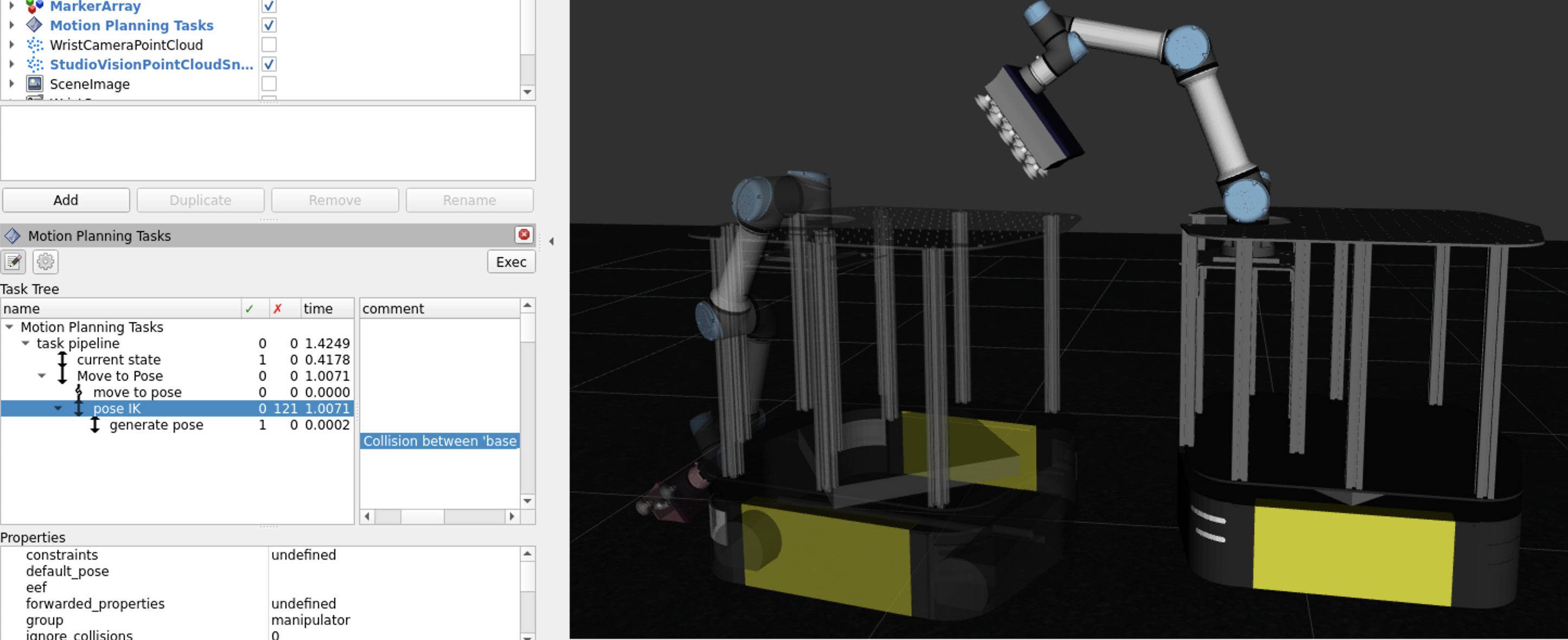
-
Read the comment field and you should see that, as expected, we put the end effector target in a position with no possible solutions. Hence, MTC failed due to collision with the floor.
-
By clicking on the comment field, each of these solutions can be viewed in the Rviz visualization window.
MTC is a powerful tool for complex planning tasks, but it may not always be the best choice. Here are some guidelines:
- Use MTC when you have a complex task that requires multiple steps, such as pick-and-place operations, where you need to plan a sequence of actions that depend on each other.
- Use other Behaviors when you have a simple task that can be solved with a single motion planner, such as moving the robot end effector to a specific pose or joint configuration, or when you need to perform a single Cartesian path planning task.
Mobile base navigation
In this section, we explore basic navigation of the mobile robot using ROS’s Nav2 stack. Nav2 provides autonomous navigation capabilities using maps and localization.
Navigate to a Location in the Hangar
-
Start the Objective
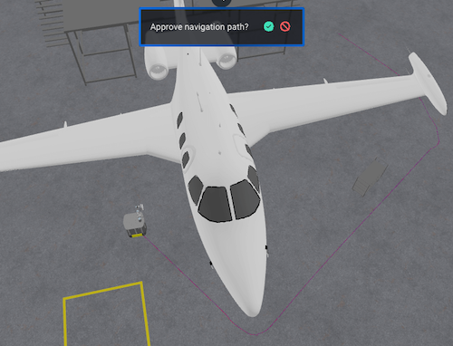
Navigate to Clicked Point. -
In the Visualization pane, click anywhere in the hangar to set a navigation goal.
-
Approve the green check mark to start movement.
-
Repeat this process to then move the robot to the yellow box zone for our next exercises.
Occupancy Grid
MoveIt Pro is able to visualize the occupancy grid, global costmap, and local costmap that is published by Nav2 in the UI.
The occupancy grid is the map that Nav2 uses to internally represent a top down view of the environment that the robot is navigating in. The occupancy grid is typically generated with some type of mapping or SLAM tool offline. The grid cells in the occupancy grid encode information if that cell is free, occupied, or unknown.
Use the Navigation toggle button (bottom-right of Visualization pane) to show and hide the Occupancy Grid, to get a better understanding of what that is.

Global Costmap
The global costmap is an internal representation of the environment where now there are costs associated with each grid cell.
These costs typically reflect safety margins around obstacles (known as the “inflation layer”) as well as additional pertinent information. The global costmap is used by a global planner to generate an end-to-end path from the robot’s current position to a goal.
Use the Navigation toggle button (bottom-right of Visualization pane) to show and hide the Global Costmap, to get a better understanding of what that is.
Local Costmap
The local costmap provides a small representation of the environment that is immediately around the robot.
Like the global costmap, the local costmap has costs associated with each grid cell. The local costmap is intended to capture dynamic changes in the environment at a much higher frequency. The local costmap is used by the local controller to generate velocity commands for the robot base so that it can follow the end-to-end path generated by the global planner while still avoiding obstacles near the robot. To learn more, see Nav2’s Environmental Representation page.
Use the Navigation toggle button (bottom-right of Visualization pane) to show and hide the Local Costmap, to get a better understanding of what that is.
The parameters for the local and global costmaps are defined under the global_costmap and local_costmap namespace in the filesystem under ~/moveit_pro/moveit_pro_example_ws/src/hangar_sim/params/nav2_params.yaml. Try adjusting the inflation_radius parameter in the file and re-launching MoveIt Pro to see the effect on both costmaps.
There are some navigation Behaviors which require providing the name of a planner or controller as an input. In Nav2, the planner is used to compute a path to complete some Objective function. Generally this means to compute a path to a goal. The planner uses the global costmap to generate the path.
In Nav2, a controller is used to generate the command velocity for the robot so that it can follow a global path. The controller uses the local costmap to generate the path such that it avoids high cost areas in the local costmap while still trying its best to follow the path.
ML-based mobile pick and place
In this last section we will explore an example Objective that involves using machine learning to detect scattered boxes, and leverage our mobile robot to move the boxes to a predefined zone in a warehouse.
This Objective requires a fairly powerful computer to run, due to its use of several ML models. It is ongoing work to improve performance of these ML models, but you may not be able to run this example without NVIDIA hardware. If you can’t run this successfully that’s ok, but take a look at the Objectives to see how things are put together.
Run the Objective ML Move Boxes to Loading Zone. Watch the robot scan a region, detect boxes, and place them in a zone.
The Objective is designed to operate in an unstructured environment. It relies on wrist camera images to extract scene information and generate a motion plan.
- First, the robot navigates to the general region where boxes are expected to be.
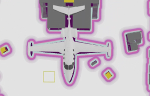
- The wrist camera images are fed through a vision language model to extract segmentation masks for all visible boxes.
- The exact prompt used for segmentation can be tuned for better performance.
- Given the masks, motion planning is initiated for each possible box to be grasped.
- Once the first viable motion and grasp is found, the robot will navigate to that box and pick it up.
- After picking up the box, the robot will motion plan to the designated loading zone and drop the box off.
Planning motion to pick up a box is an interesting example of MTC usage, where the task is to find a valid pose on the box to apply suction to, and then plan a collision-free trajectory to that pose. 'Vacuum" pose candidates are computed via the GenerateVacuumGraspPoses Behavior. The MTC task then evaluates all those poses and chooses one that is valid and optimizes the overall path length.
It is worth noting the SetupMTCBatchPoseIK Behavior, which is the MTC-equivalent of the ComputeInverseKinematics Behavior we saw earlier.
It allows us to compute multiple IK solutions and feed them as candidates to the MTC task.
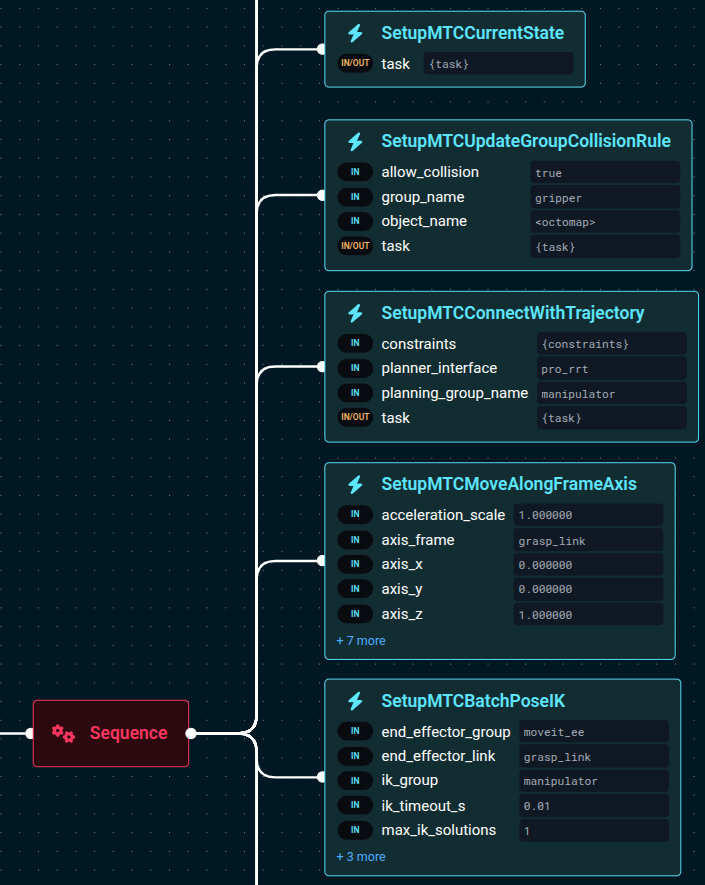
This specific MTC task, reading it from the bottom up, does the following:
- Computes IK candidates for the vacuum poses on the box, thus feeding the pipeline with multiple target joint-space configurations.
- Checks that from the target pose there is a straight-line Cartesian path to move vertically, i.e. an 'approach' motion.
- Checks that the beginning of the 'approach' motion can connect, in joint-space, to the current robot joint state.
- Disables collisions between the robot vacuum gripper and the 'octomap', which is a sensor-based 3D representation of the environment. This tells the planner that collisions with the boxes are allowed, since we are trying to pick them up.
Summary of Motion Planning and Control Approaches
Here's a summary of the types of motion control available in MoveIt Pro and the corresponding Behaviors and Subtrees that can be used to achieve them.
| Motion Planning Type | Collision Aware? | Behavior Input Type | Example Usage |
|---|---|---|---|
| Joint Interpolation | No* | GeneratePointToPointTrajectory moveit_studio_agent_msgs::RobotJointState | Interpolate to Joint State |
| Global Freespace Planning | Yes | PlanToJointGoal moveit_studio_agent_msgs::RobotJointState | Move to Joint State, Move to Waypoint |
| Global Freespace Planning | Yes | SetupMTCPlanToPose geometry_msgs::PoseStamped | Move to Pose |
| Inverse Kinematics (IK) Solver | Yes | ComputeInverseKinematics std::vector<geometry_msgs::PoseStamped> | Compute IK, Plan and Move** |
| Cartesian Planning | No* | PlanCartesianPath std::vector<geometry_msgs::PoseStamped> | Cartesian Draw Geometry From File** |
| Cartesian Planning | Yes | SetupMTCPathIK (8.7 or newer) std::vector<geometry_msgs::PoseStamped> | Plan Path Along Surface (factory_sim only) |
| Any*** | No*** | PlanMTCTask moveit::task_constructor::Task | Move to Pose |
* Can check a generated trajectory for collisions with ValidateTrajectory
** hangar_sim example only
| Controller Type | Collision Aware? | Behavior Input Type |
|---|---|---|
| Joint Trajectory Controller | No | ExecuteFollowJointTrajectory trajectory_msgs::JointTrajectory |
| Joint Trajectory w/Admittance Controller | No | ExecuteTrajectoryWithAdmittance trajectory_msgs::JointTrajectory |
| Cartesian Velocity-Force Control | No | PublishVelocityForceCommand moveit_pro_controllers_msgs::VelocityForceCommand |
| Protected Cartesian Velocity-Force Control | Yes | PoseJog moveit_pro_controllers_msgs::VelocityForceCommand |
| Any*** | No | ExecuteMTCTask moveit_task_constructor_msgs::Solution |
***Dependent on the MTC stages.
| Coverage Path Generation | Collision Aware? | Behavior Input Type |
|---|---|---|
| 2D Rectangle | No | GenerateCoveragePath geometry_msgs::PoseStamped |
| Point Cloud Contour | No | GetContourFromPointCloudSlice PointCloud and PoseStamped |
Summary
In this tutorial, we explored the core concepts and practical workflows for motion planning in MoveIt Pro. We covered the differences between joint-space and Cartesian-space planning, how to create and execute trajectories, and how to plan around obstacles using both mobile base navigation and arm manipulation. We introduced advanced planning techniques such as coverage path planning, scan-and-plan workflows, and the MoveIt Task Constructor (MTC) for multi-stage tasks. Finally, we demonstrated the integration of machine learning for perception-driven pick-and-place operations, showcasing how MoveIt Pro unifies navigation, perception, and manipulation in complex robotic applications.
🎉 Congratulations!