Example UR5 Hardware Setup Guide
This tutorial is an example of how to configure a UR5e robot to run MoveIt Studio. It covers hardware requirements, steps for setting up the arm, gripper, and camera, and payload and network configuration.
Note
This tutorial uses the UR5e arm as the primary example, but any of the UR e-series arms will work. Older CB3 model UR arms can also be made to work with MoveIt Studio with the integration of an external force/torque sensor, but that process is not covered in this tutorial.
Other brands of arms are also compatible with MoveIt Studio, but they must have a ros2_control based driver. PickNik has assisted in writing ROS 2 drivers for several brands of arms. Please contact us if you are interested in hiring PickNik to write a ROS 2 driver for your arm.
Required Hardware
The MoveIt Studio Technical Specifications Document details the hardware and software requirements for running MoveIt Studio along with a list of the current features.
Aside from the arm, other required hardware includes a gripper, at least one RGBD camera, and a wrist camera mount. The default gripper supported by MoveIt Studio is a Robotiq 2f 85 model gripper and the default RGBD camera is the Intel RealSense D415 or D435 camera. PickNik has created a custom wrist camera mount for RealSense cameras which can be downloaded and 3D printed.
The full list of parts needed to perform this hardware installation is:
- 1x computer to run MoveIt Studio and robot drivers
- 1x ethernet cable
- 1x UR e-series robot arm
- 1x Intel Realsense D415 wrist camera
- 2x screws each for attaching camera to camera mount
- 1x 3m or longer dual screw locking USB C cable
- 2x velcro strap
- 1x custom wrist camera mount for RealSense D415
- 1x Robotiq 2f 85 model gripper
- 4x hex screws for attaching gripper coupling to wrist (ideally with washers)
- 1x retaining pin to drop into 5th hole
- 4x Phillips head screws for attaching gripper to gripper coupling
- Robotiq gripper cable with USB serial adapter
The following sections detail how to get all of the required hardware connected and running MoveIt Studio.
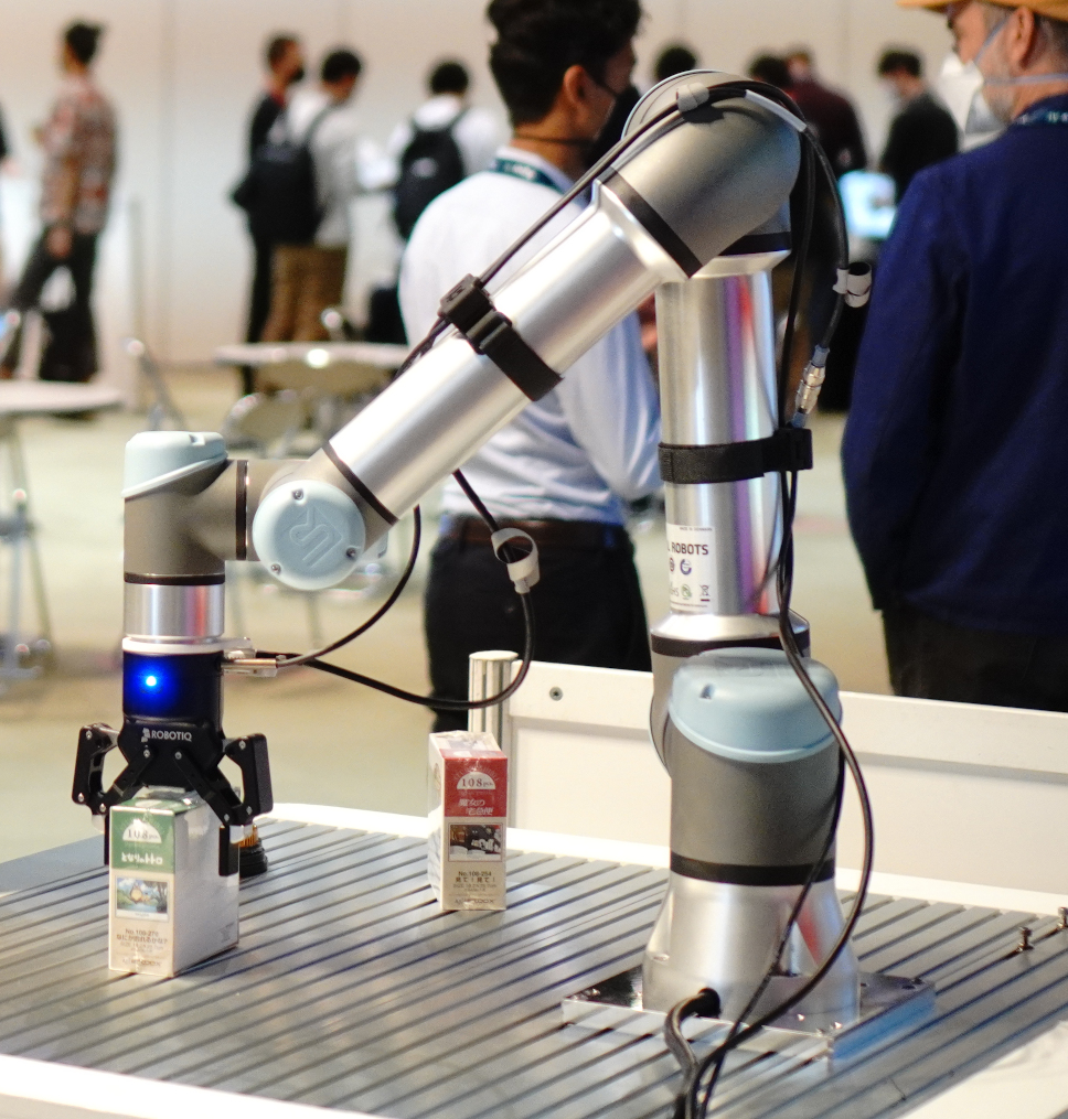
1. Assemble the Arm Hardware
The UR5e comes in two boxes, one that contains the arm and one that contains the control box and attached teach pendant.
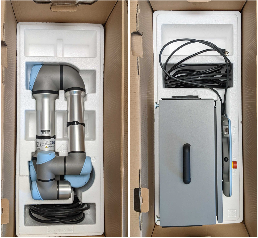
Unbox the arm and mount it on your table, stand, or platform of choice. We recommend mounting the arm with the cable coming out of the robot’s “left” side. This will ensure that the base joint is at 0 degrees when the arm is facing “forward”. MoveIt Studio constrains the base joint to +/- 180 degrees, so this puts the base joint in the middle of its range of motion.
Before continuing, verify that the robot is mounted securely and has sufficient space to operate in.
Next, unbox the UR control box. You will need to connect the robot cable to the control box and the arm. Make sure the connectors on both ends are locked before connecting the control box to power.
Finally, plug in the power cable to the bottom of the control box, but do not turn the arm on until connecting peripherals (described in the next section).
2. Connect the Gripper and Wrist Camera
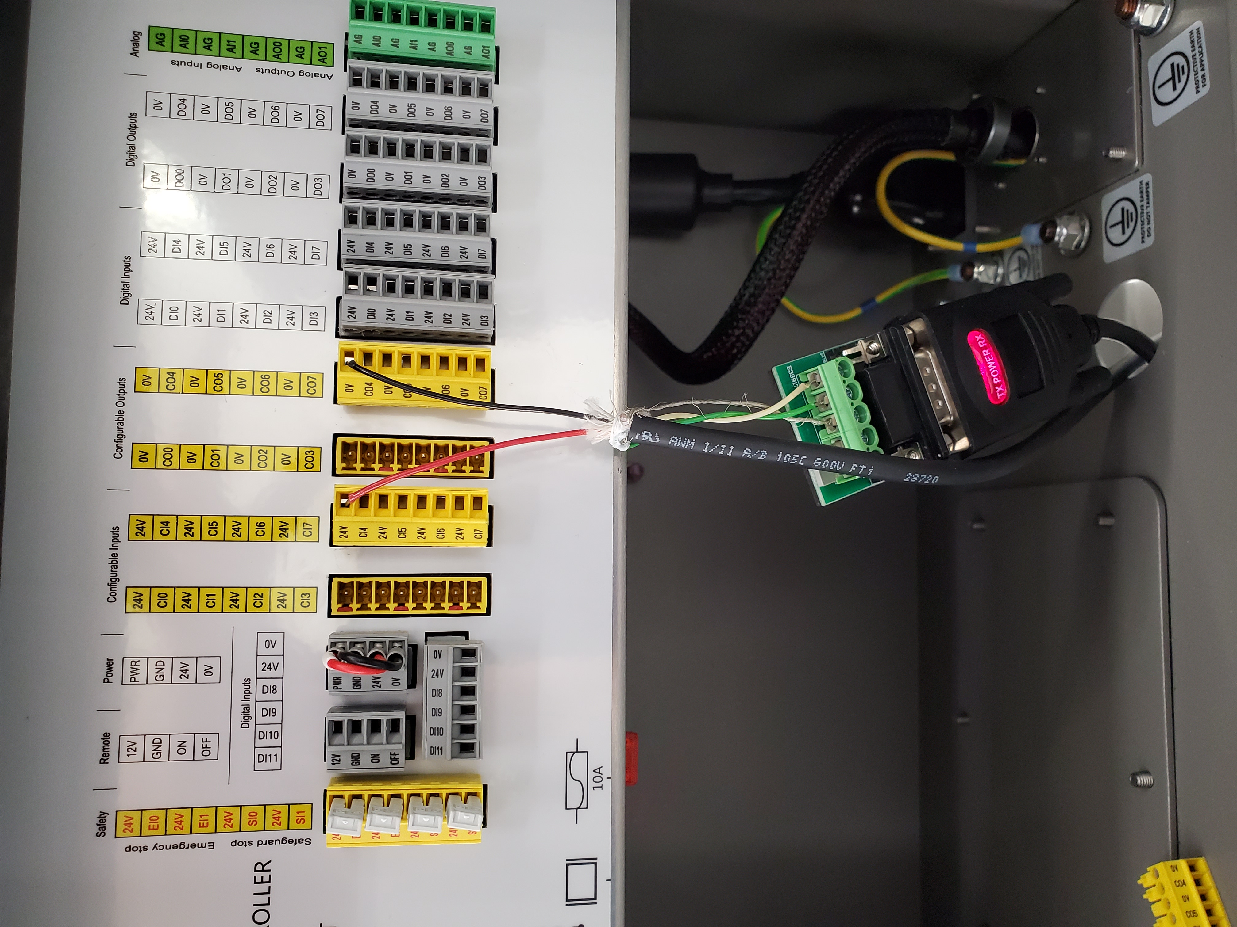
UR Control Box
Now, you will need access to the UR control box, which can be opened using the provided key.
First, connect an ethernet cable to the port inside the control box. Run the other end of this cable through the hole in the bottom of the box and connect to the computer. This connection is used to control the arm.
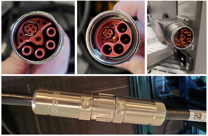
Next, connect the Robotiq 2f-85 gripper to the control box. The gripper comes with a cable and USB-to-serial converter. Run the end of the cable through the hole in the bottom of the control box and connect it like this:
The USB connection coming out of the cable gets plugged into the computer.
Finally, MoveIt Studio requires a wrist-mounted camera, which will be plugged into the computer.
Multiple cameras can be connected, but only one is required to run Objectives that rely on depth information.
End of Arm Assembly
All pieces of the gripper must first be aligned before attaching the entire assembly to the end of the arm at once.
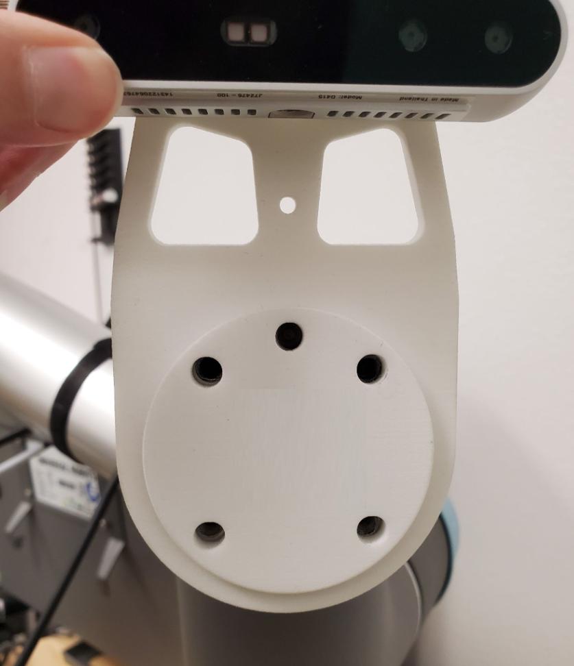
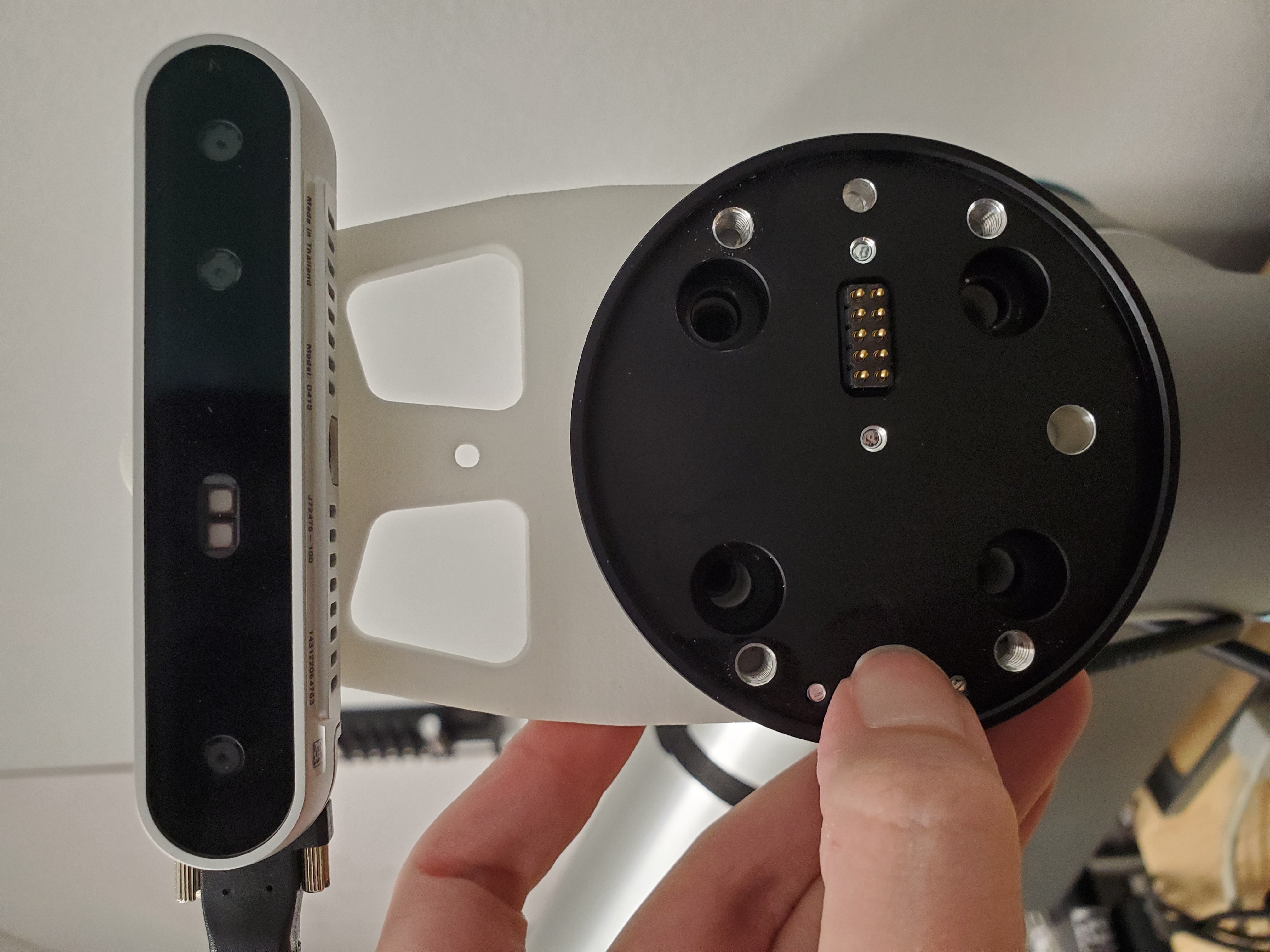
The camera mount is the first piece in the assembly and it connects directly to the end of the arm. The holes in the mount must be aligned with the screw holes on the end of the UR5e.
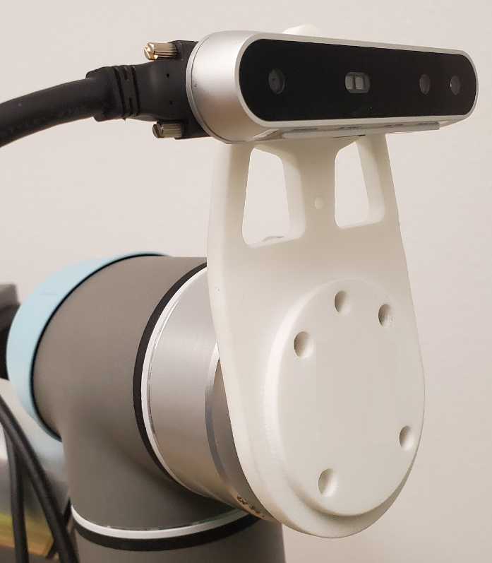
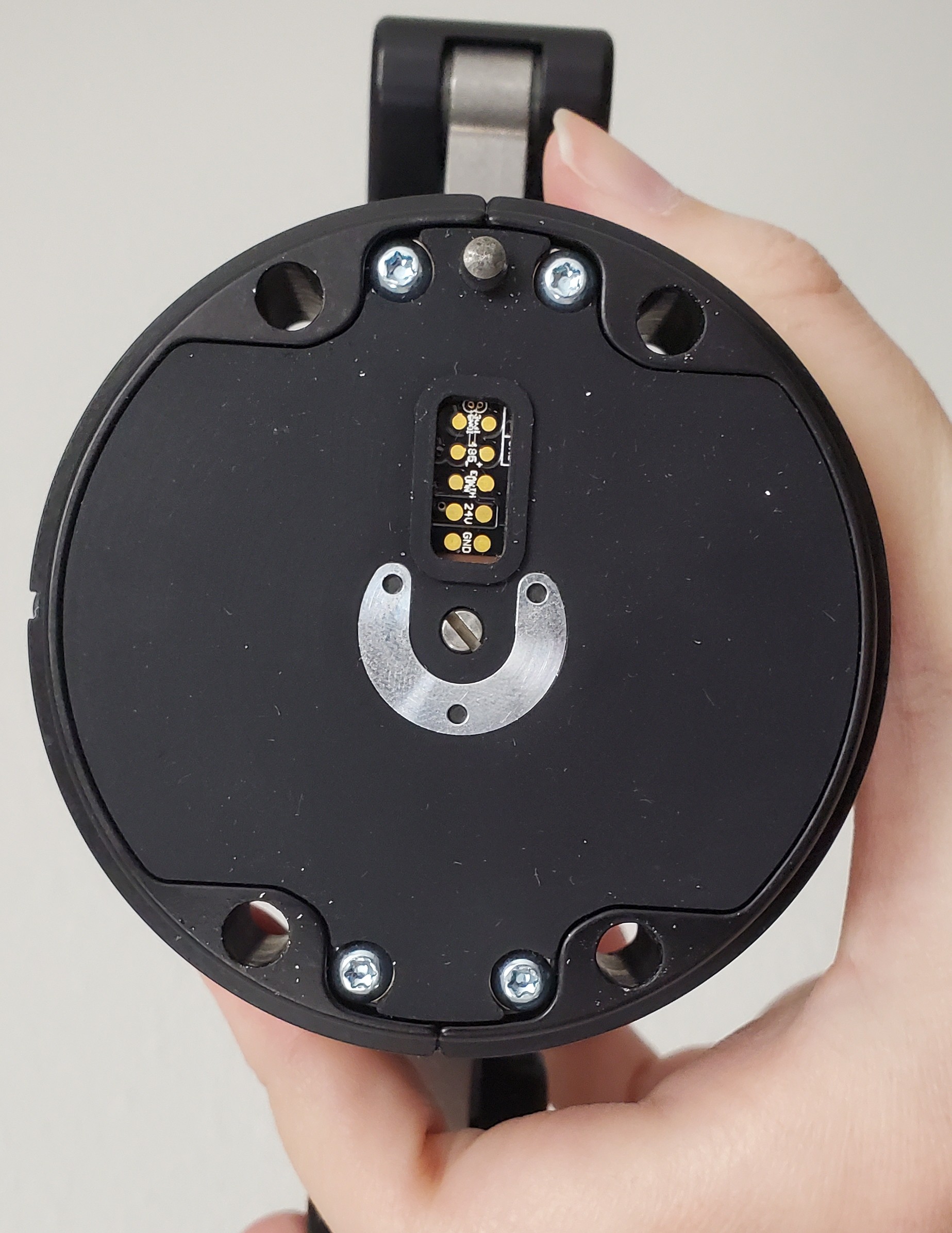
Next comes the gripper cable and then the gripper. These two pieces must be aligned to each other and aligned with the camera mount.
Once all three pieces are in place, use four extra-long screws to attach the entire assembly to the end of the arm. When attached correctly, the camera and gripper cables will be coming out of the same side of the end-effector and the LED on the gripper will be facing the ground.
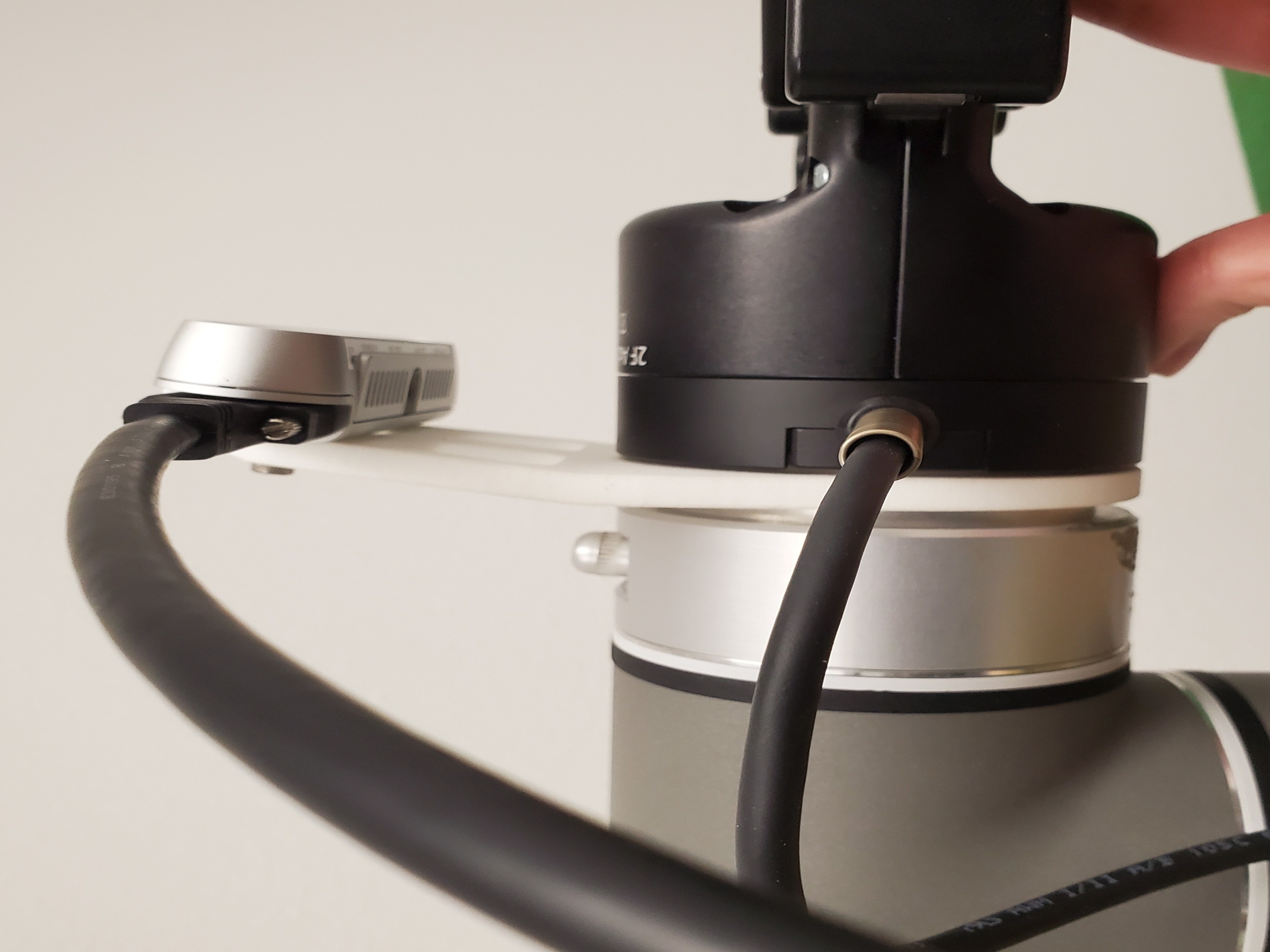
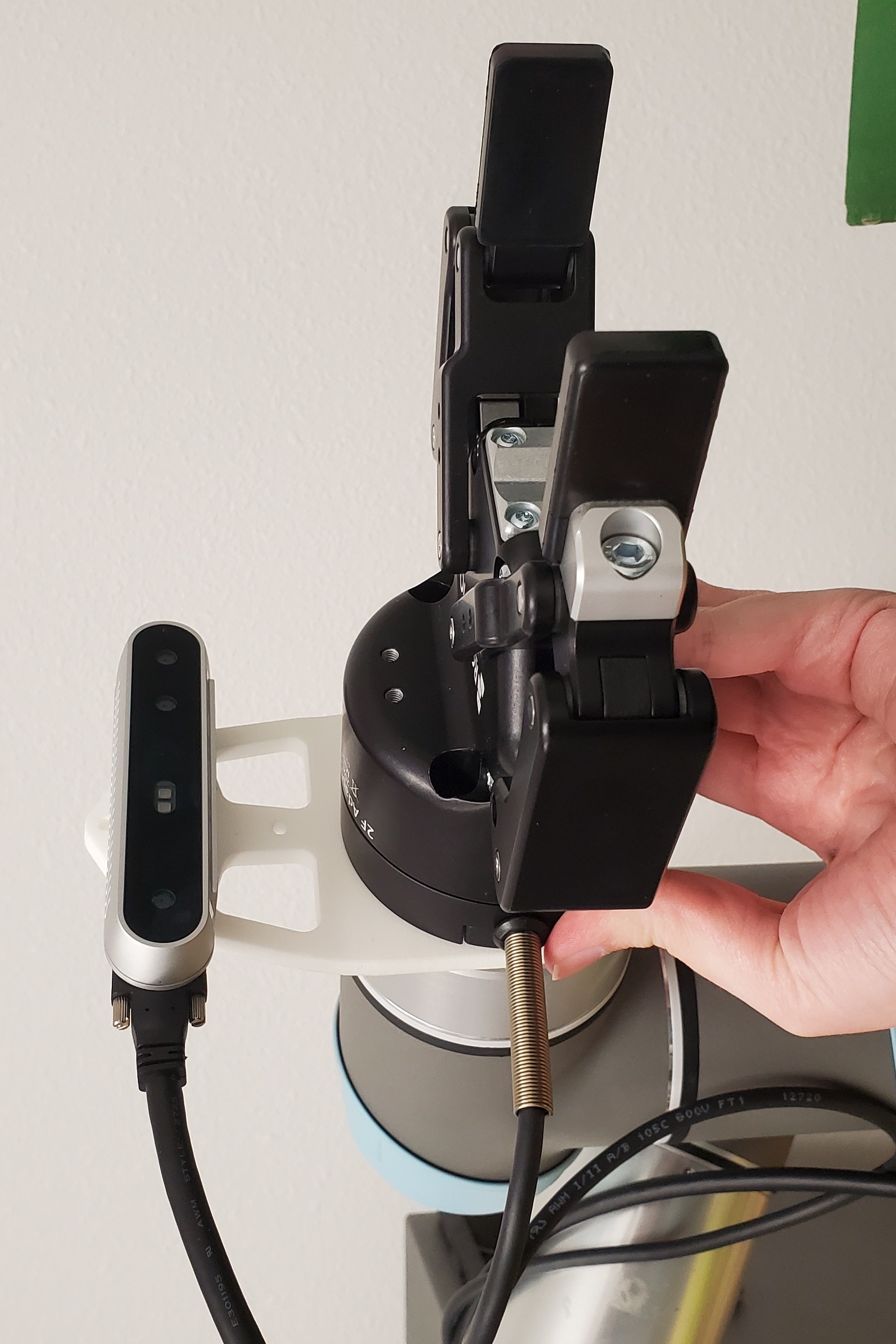
Once the gripper and camera are securely mounted, attach the 2 velcro straps and use them to route the gripper and camera cables down the length of the arm, ensuring there is enough slack that large movements will not cause the cables to be pulled taut.
3. Set Up Computer
For the best hardware performance for the UR5e, we recommend setting up the control computer to run Debian Bullseye. We use this OS to take advantage of the real-time kernel for commanding the robot hardware. Detailed installation instructions can be found in this guide.
4. Connect Computer
The computer has two network interfaces: one to connect to the Internet and another to connect to the robot’s Control Box via a peer-to-peer network.
At this point, you should have made the following cable connections:
Computer
- Power cable
- Ethernet cable for LAN
- Ethernet cable to UR Control Box
- USB cable to Robotiq gripper
- USB cable to Realsense wrist camera (+ cables to any additional cameras)
UR Control Box
- Power cable
- 2x yellow Robotiq power combicon
- Ethernet cable to computer
5. Change Computer Network Settings
With the computer set up and connected to the robot and local network, we will now set IP addresses for each of the ethernet connections.
The computer has two network interfaces (one to connect to the Internet and another to connect to robot’s Control Box), and each needs a different connection profile. To set these up, click the arrow at the upper right corner of the screen, and then click “Settings” > “Network”.
First, unplug the ethernet cable between the computer and your network infrastructure. One of the two Wired interfaces will now show up as “Cable unplugged”. Click the gear icon next to that Wired adapter. - Under the “Identity” tab, give this profile a name (like “Internet”). - Click “Apply” to accept the default values for the other settings. - Plug the ethernet cable back in.
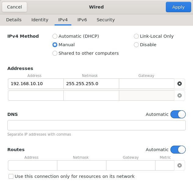
Now, click the gear icon next to the other network adapter. - Under the “Identity” tab, assign a name to the connection profile, such as “Robot”. - Under the “IPv4” tab, select “Manual” as the “IPv4 Method”. - Enter 192.10.0.12 for the Address, and 255.255.255.0 for the Netmask. - Click “Apply”.
6. Boot the Arm, Update Software, and Change Pendant Network Settings
Now that the hardware is fully assembled and connected to power, press the power button on the robot’s teach pendant to turn it on. It will take a few moments to boot up and then you will see this prompt on the screen:
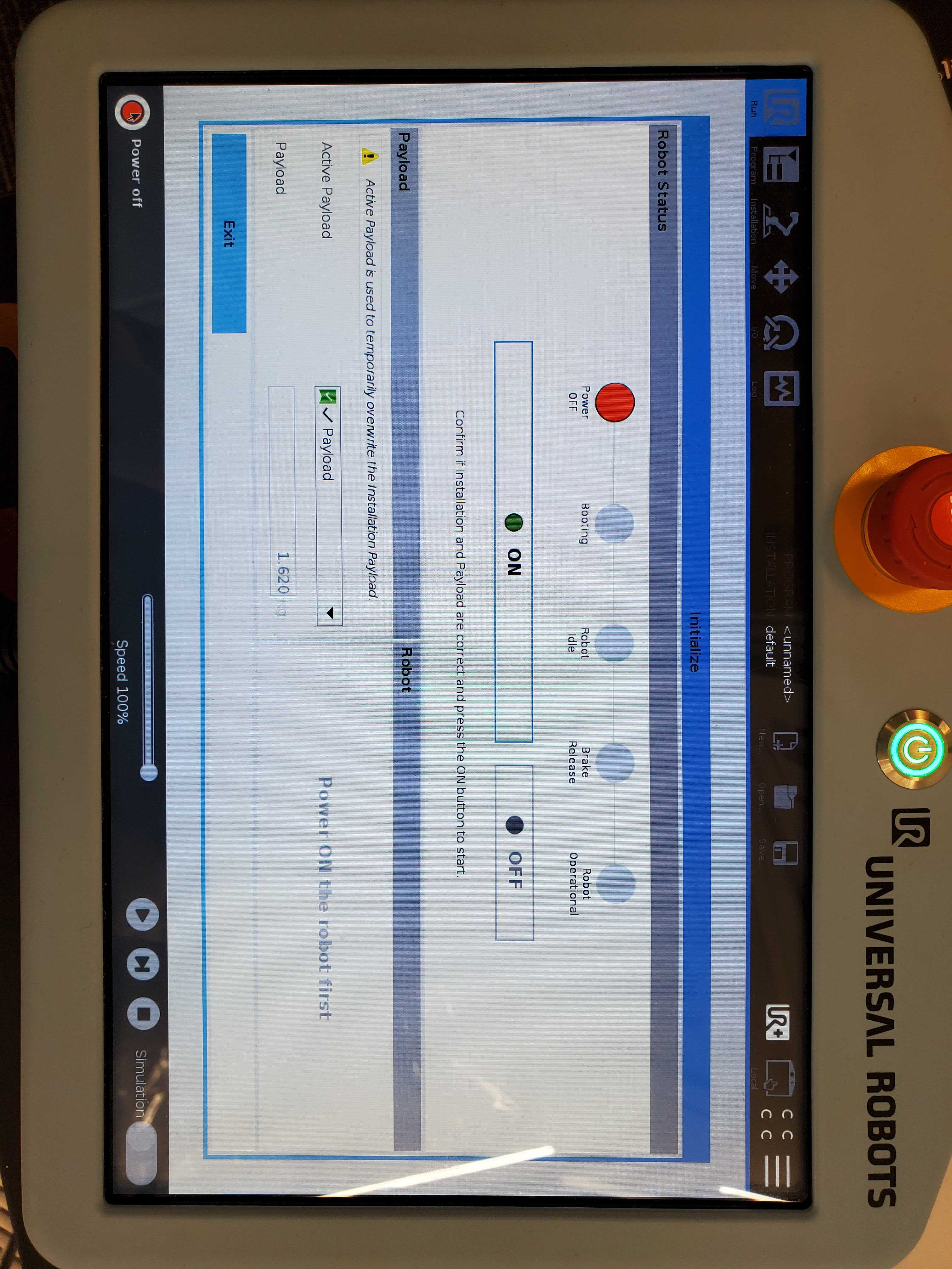
Click “On”, wait for the booting step to complete, and then press “Start” to release the brakes and enable the arm. Press “Exit” to close this popup.
Before continuing, ensure that the correct software version is installed! MoveIt Studio requires Polyscope version 5.5.1 or newer for the e-series arms and version 3.12.0 or newer for CB3-series arms.
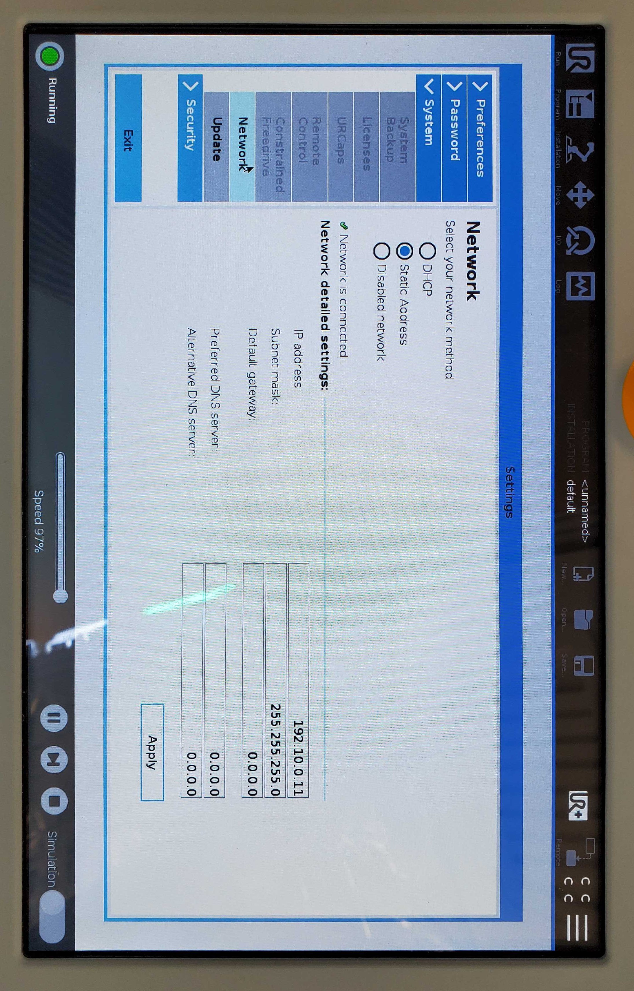
Then, you will need to configure the robot’s network to work with your computer. Go to the hamburger menu and go to “Settings” > “System” > “Network”.
On this screen you want to select “Static Address” as the network method and enter 192.10.0.12 for the IP address and 255.255.255.0 for the Subnet mask. Leave the default value of 0.0.0.0 for all other fields.
7. Update Safety Settings
To find the safety settings, go to the “Installation” tab and click “Safety” to expand the submenus. Under “Robot Limits” there is the option to set custom safety limits or to select from 4 “Factory Presets”, which range from “Most Restricted” to “Least Restricted”. We recommend using the 3rd preset, or second least restricted option, for the best performance.
To change this setting, you will need to enter the Safety Password for the robot. For new robots, users are prompted to set a Safety Password upon setup. To reset a forgotten password, follow the steps shown here.
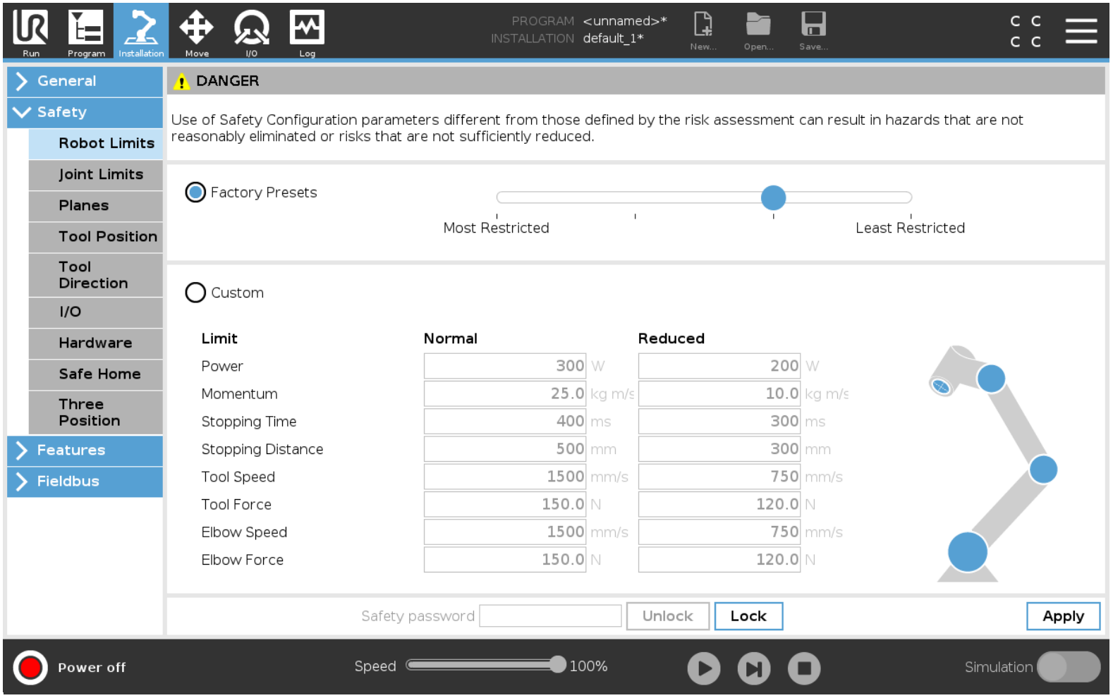
Once you have changed the settings, click “Apply” in the bottom right corner to save these settings.
8. Calibrate the Payload
Due to the added weight of the camera and gripper on the end effector, the arm will need to be run through the UR payload calibration routine to ensure the calculated payload value is correct. The accuracy of this value becomes important when running MoveIt Studio objectives that rely on force feedback. A video showing how to perform this process is available here, but below are the high level steps.
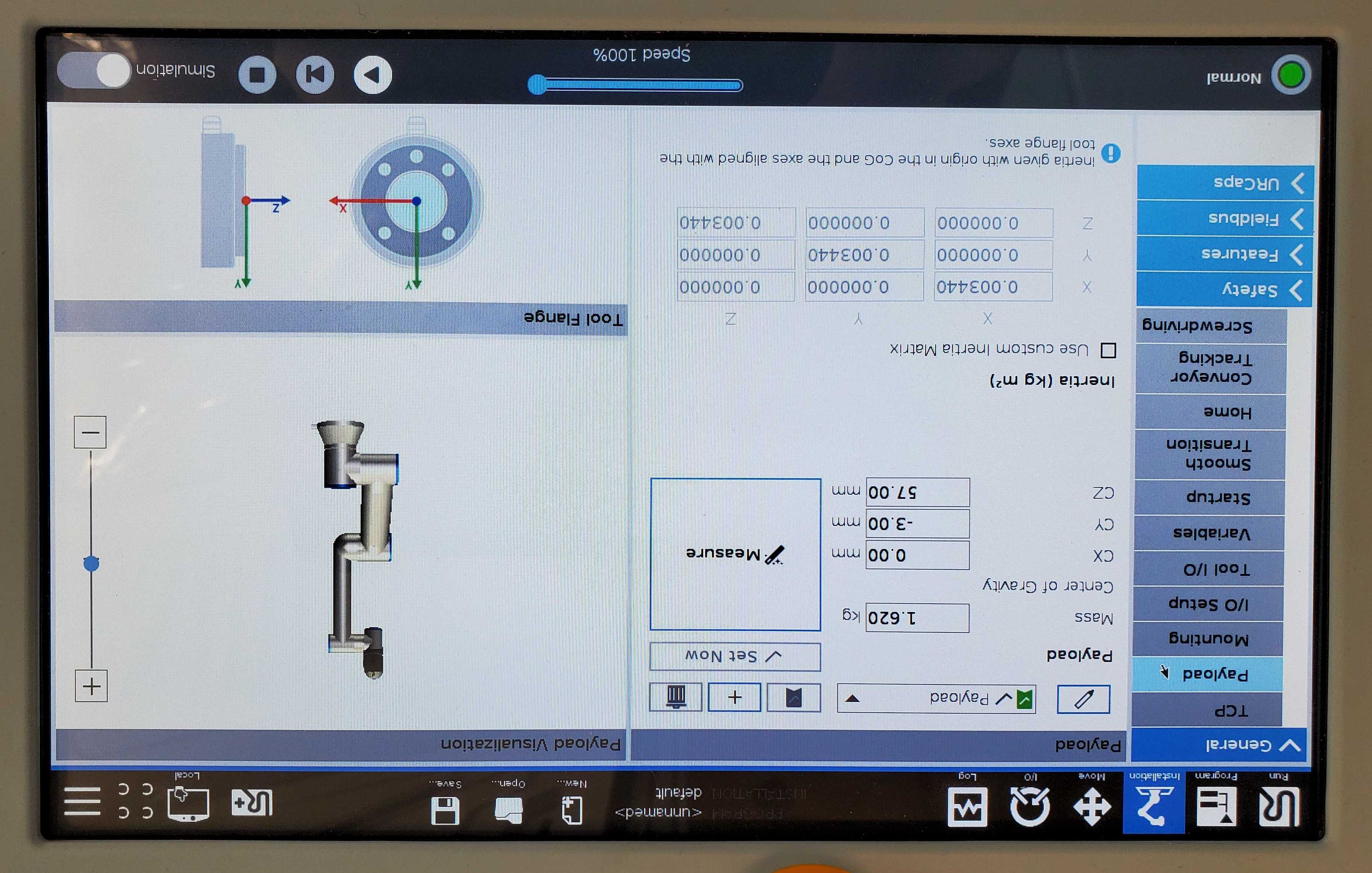
To run the calibration routine, go to the “Installation” tab and under “General” click on “Payload”. Then, click “Measure”.
This will prompt you to move the arm into a series of four poses to calculate the payload. Try to make the poses as varied as possible for the most accurate results.
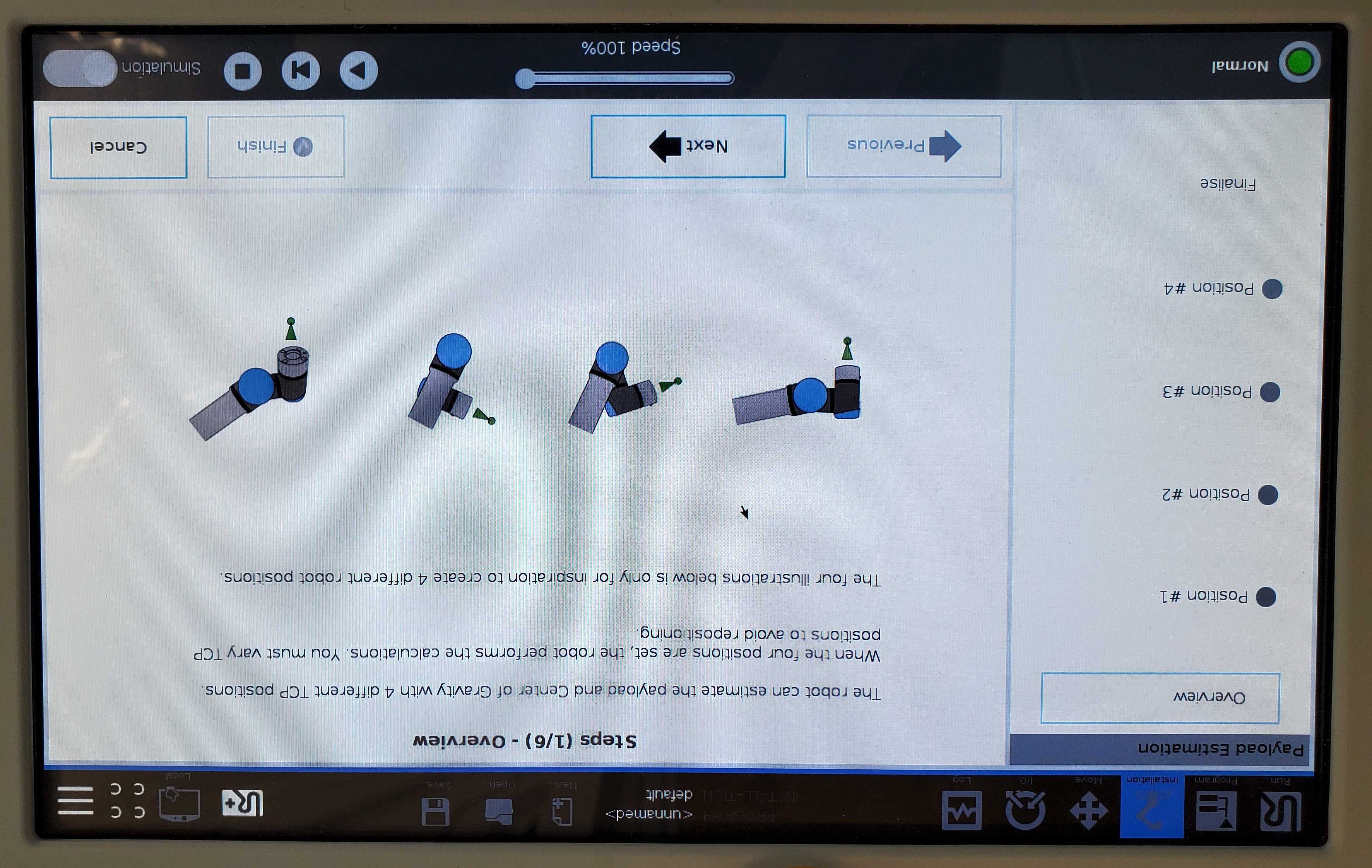
The next screen will prompt you to set Position #1. Click “Set Position” and use free drive mode to move the end effector to the desired pose. Then, click “Ok”. Repeat for positions 2-4. Once Position #4 is set, the payload will be calculated.
An example payload configuration output with a Robotiq 2F-85 gripper looks similar to this:
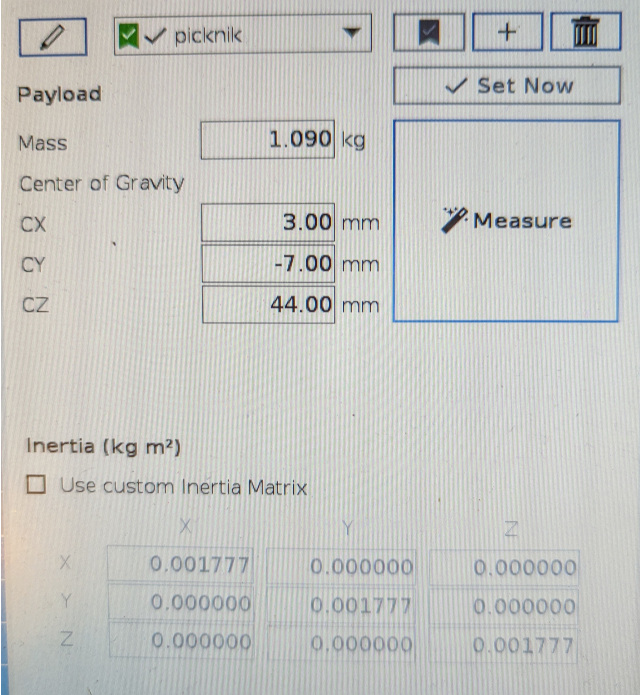
Make sure to save the calibration data at the end of this routine! If it is not saved, the data will be lost if the arm loses power or gets restarted and the routine will have to be run again.
9. Update your RealSense camera firmware
First, ensure that the required realsense packages are installed on your host. Follow the Realsense instruction to install their debian packages.
Then make sure your RealSense camera’s firmware is up-to-date!
Even if the hardware is new to you, it may be running an old firmware version.
You can use the realsense-viewer application to test and update your firmware.
Follow the RealSense firmware upgrade guide
10. Use the Arm with MoveIt Studio
As a final check, ensure that the USB connector from the gripper, the ethernet connection for the arm, and the camera cable(s) are connected to the computer.
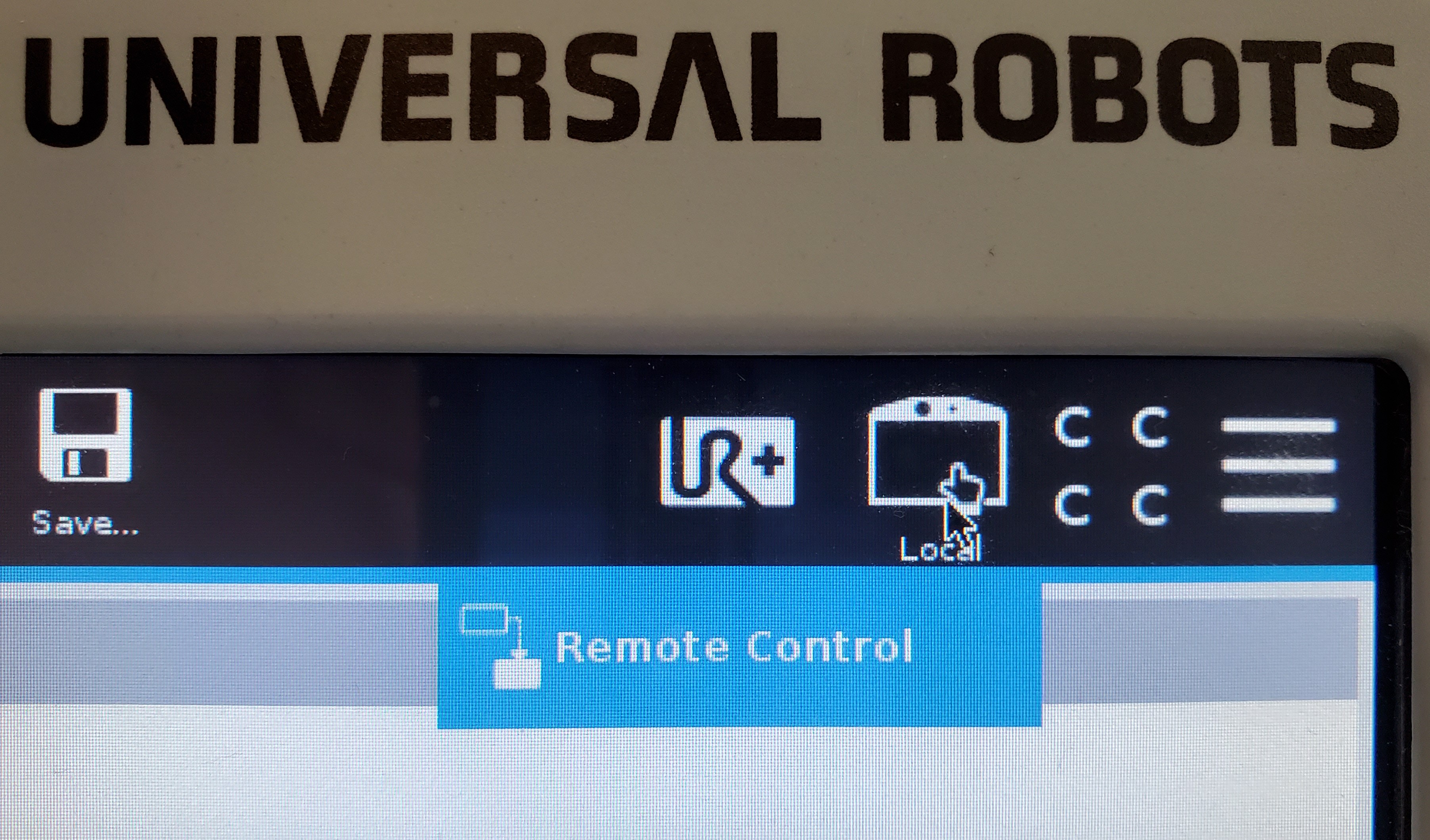
Now the arm must be switched from local mode to remote mode to enable remote control. On the top right corner of the screen, next to the hamburger menu, there will be an icon of a teach pendant, with either the word “Local” or “Remote” below it. If it shows “Remote”, no further action is necessary. If it shows “Local”, tap on the icon, and select “Remote Control” from the dropdown menu.
Your hardware is now ready for use with MoveIt Studio! Please see Configuring MoveIt Studio to Run on Hardware for next steps.