2. Perception & Advanced Motion Planning
🕒 Duration: 1-2 hours
Tutorial Overview
This tutorial dives into the advanced perception and motion planning capabilities of MoveIt Pro. Building on the foundational skills from Tutorial 1, you'll learn how to use computer vision tools like AprilTags, point cloud registration, and segmentation to enable your robot to perceive its environment. You'll also explore how to structure complex task plans using Behavior Trees and leverage the MoveIt Task Constructor (MTC) to handle sophisticated manipulation tasks. Whether you're stacking blocks, identifying parts, or debugging planning failures, this tutorial will guide you through practical workflows and best practices.
Pre-reqs
You should have already installed MoveIt Pro. We will assume you have already completed Tutorial 1 and have basic familiarity with the software.
Start MoveIt Pro
Launch the application using:
moveit_pro run -c lab_sim
Perception Approaches In MoveIt Pro
In highly structured environments you might be able to program your robot arm to do things like basic pick and place without any perception. However, for most robotics applications today having cameras and computer vision is crucial.
In our world view of robotics there are roughly 4 main categories of perception:
- Fiducial Marker Detection (e.g. AprilTags)
- Classic computer vision (e.g. OpenCV)
- Point Cloud Segmentation (e.g. PCL)
- Machine Learning (e.g. SAM2)
MoveIt Pro no longer ships with examples of classic computer vision, due to the rapidly evolving AI landscape. However we do ship with many examples of the other three approaches to perception. We will demonstrate these in the following sections:
Fiducial Marker Detection with AprilTags
In this exercise we will build a new application that will use AprilTags to detect and stack blocks.
AprilTags are a type of fiducial marker system commonly used in robotics and computer vision. They consist of black-and-white square patterns that can be easily detected and uniquely identified by a camera. In robotics, AprilTags are often used for precise localization and pose estimation of objects in the environment. AprilTags are particularly useful in applications requiring low-cost, reliable visual tracking without the need for complex sensors.
Initialize the Robot and Scene
First, create a new Objective called Stack Blocks and set the category to Course 2. If you’re unsure how to create a new Objective, please refer to the Tutorial 1.
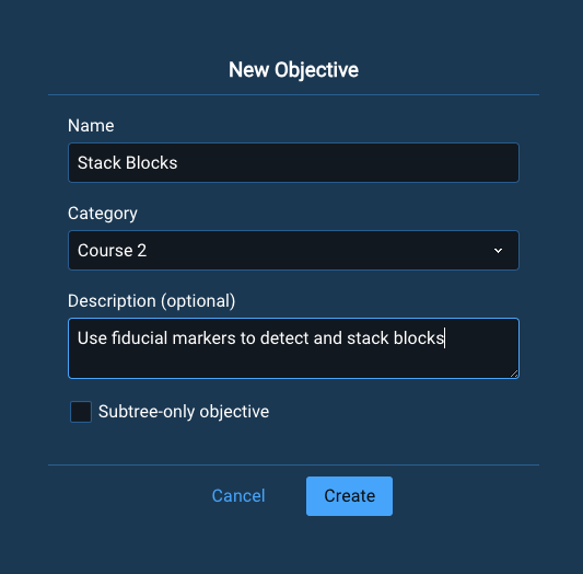
Once created, remember to delete the AlwaysSuccess Behavior from your new empty Objective.
Take make this tutorial quick and easy, we will use a lot of pre-built subtrees that ship with MoveIt Pro. Add the following four subtrees to the default Sequence:
Open GripperLook at tableClear SnapshotTake wrist camera snapshot
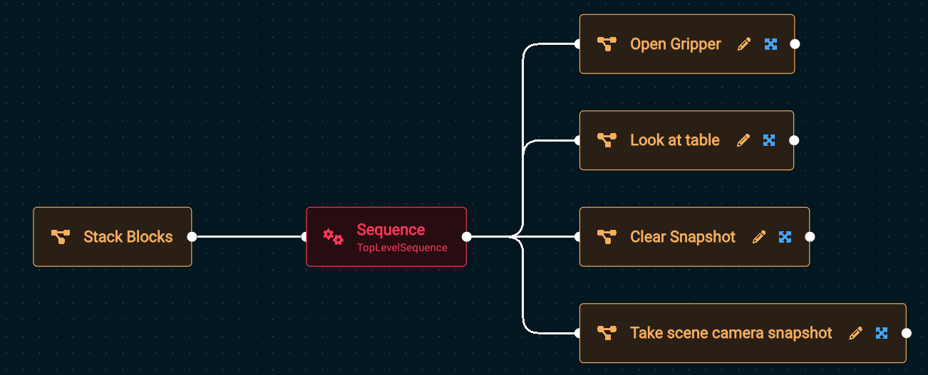
When finished, Run the Stack Blocks Objective. You should see the robot reset its end effector, move to its home position, clear out any previous depth sensor readings, then take a fresh depth sensor reading using its wrist camera (not the scene camera).
Get Object Pose from AprilTag
The next step for us in the Stack Blocks Objective is to detect the pose of a block, by using the block's AprilTag to locate it.
- Edit the
Stack BlocksObjective that you began above. - Add a
Sequencenode to help us organize our Behavior Tree as it grows.
As your application gets more complex, we recommend you use sequences and subtrees to manage the complexity with nicely labeled abstractions.
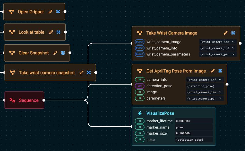
Add the following three subtrees/Behaviors to the newly added Sequence, tweaking the parameters to some of the Behaviors as described below:
Use the dropdown selectors to make building your Behavior Tree faster.
Take Wrist Camera ImageGet AprilTag Pose from Image- Set the
camera_infoto{wrist_camera_info}. - Set the
imageto{wrist_camera_image} - Set the
parametersto{wrist_camera_parameters}
- Set the
VisualizePose- Set the
poseto{detection_pose}
- Set the
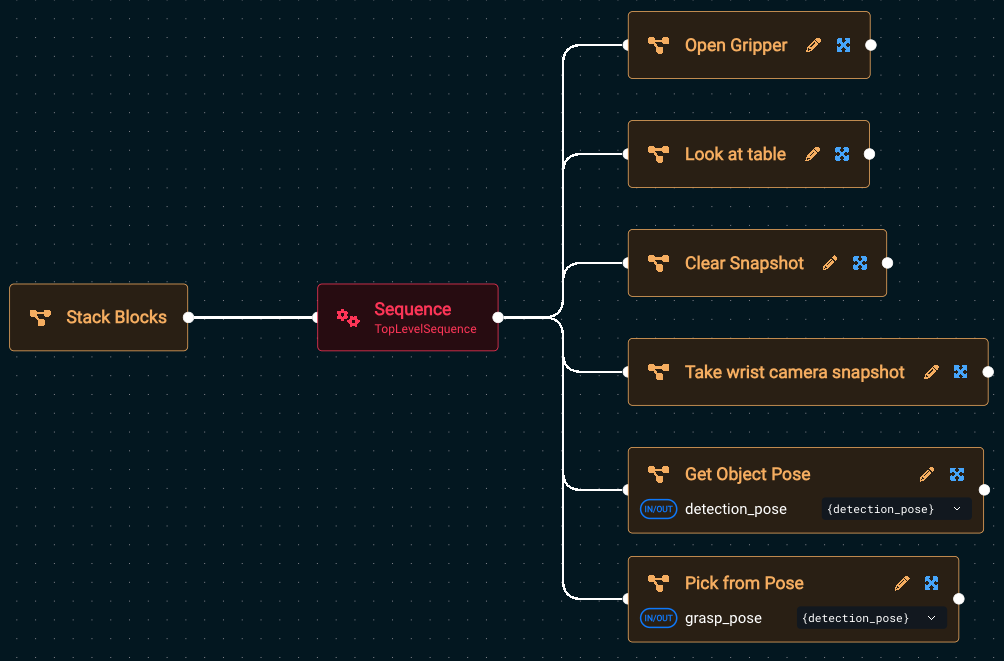
Your tree should look similar to this now (zoomed in):
If you want to know more about how each Behavior works, you can see the built-in descriptions in two locations. Either:
- When you hover over a Behavior in the left sidebar
- When you click on a Behavior and the parameter sidebar opens on the right. The right sidebar is also useful in that it shows you all the input and output ports, along with their port descriptions.
Now Run your Stack Blocks Objective, and you should see a 3-axis colored pose marker appear on the detected block:
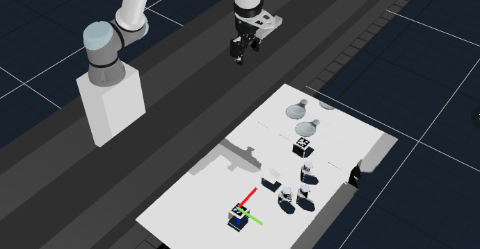
Your simple AprilTag perception approach is in-place, great job so far!
Pick from Detected Block Pose
Next to pick the block:
- Edit again your
Stack BlocksObjective. - Add the
Pick from Posesubtree to the bottom of the rootSequence.- Set its
grasp_poseto{detection_pose}using the dropdown box to easily auto-complete.
- Set its
- Run the Objective again
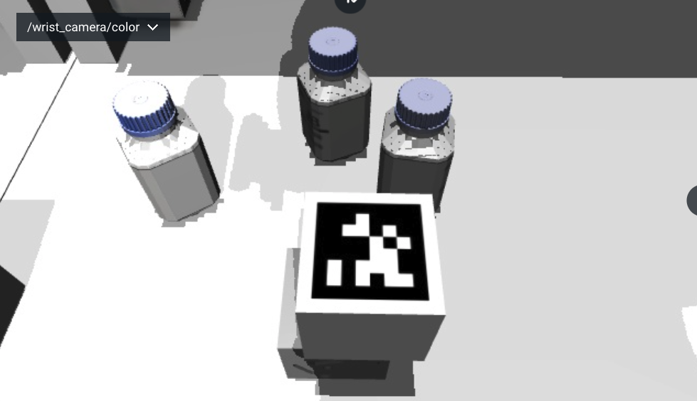
You can't really see if the grasp was successful in the Visualization pane since we are not leveraging attached collision objects to add grasp information to the planning scene in this example, but if you look at the /wrist_camera/color view pane you should see that the block is between the robot's two fingers:

Why are the camera feeds so pixelated?
Some folks have asked us why the above image is low quality, and we're happy to explain. We've purposefully turned down the rendering quality to make MoveIt Pro more performant for the most generic set of customer's computers. We don't require that you have a GPU for many of our applications, for example. It's too advanced for this tutorial, but know that the rendering can certainly be increased if your computer can handle it.
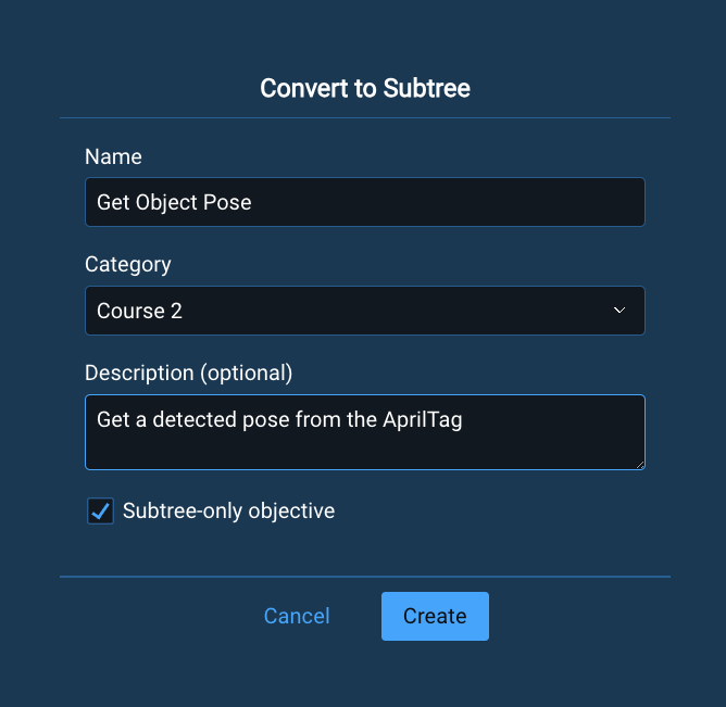
Create a Subtree
At this point our behavior tree became more complex, so let's convert the previous Sequence into a subtree.
Subtrees are modular components within a larger Behavior Tree that encapsulate a set of actions or decision logic. By allowing one Behavior Tree to reference another, subtrees enable greater reusability, organization, and maintainability in complex robotic applications. They help abstract away lower-level details, reduce duplication of nodes, and make it easier to manage common sequences or Behaviors across different Objectives. In MoveIt Pro, subtrees are especially useful for structuring sophisticated task plans in a clean and scalable way.
-
Click on the child
Sequence(not the parentSequence) -
Click on the
Create Subtreeicon that appears on top of the node
-
Name the subtree
Get Object Pose -
Set the category again to
Course 2 -
Keep the Subtree-only Objective checkbox checked
-
Click Create
The Subtree-only Objective checkbox means that this Objective can only be run as a subtree within another Objective, not as a stand-alone Objective.
After converting to a subtree, the Stack Blocks Objective should look like:
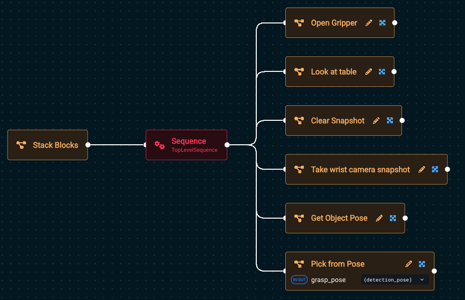
Did we miss anything? Run the Objective to see if it works.
You should see an error message that looks like this:
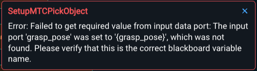
This is expected because we forgot to setup port remapping for our new subtree. A great segue to our next lession.
Port Remapping
Port remapping in Behavior Trees allows you to reuse generic nodes by dynamically assigning their input/output ports to different blackboard entries, depending on the context in which they're used. This makes Behavior Trees more flexible and modular, enabling the same node or subtree to be used in different contexts across various parts of the tree without changing its internal logic.
- Go into edit mode of the
Get Object Posesubtree- We recommend you do this by first editing
Stacked BlocksObjective then clicking the pencil icon on theGet Object Posesubtree. However you can also search for the subtree directly in the list of available Objectives, you just won't be able to switch between the parent and child Behavior Tree as easily.
- We recommend you do this by first editing
- Choose the root node (also called
Get Object Pose). - In the popup sidebar, click the + button to add an output port, to allow the the sharing of the AprilTag pose that was detected.
- Set the
Nameof the port todetection_pose - Set the
Default Valueof the port to{detection_pose}
It should look something like this:
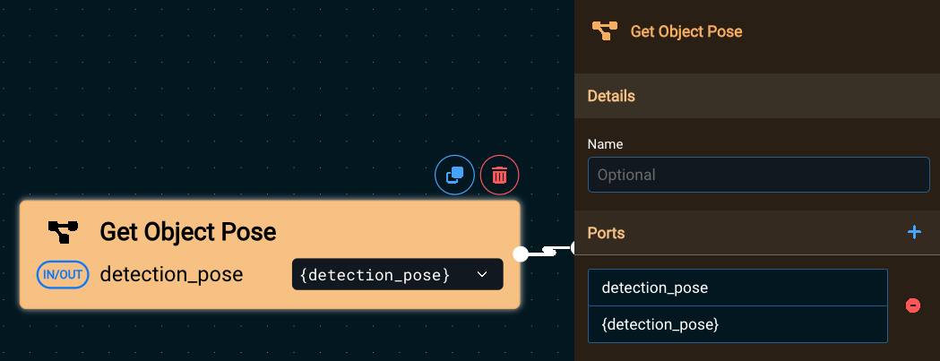
The Default Value is the name of the variable that will be used on the parent tree’s blackboard.
Click out of the sidebar, somewhere in the Behavior Tree editor area, to close the sidebar.
Now go back to editing the parent Stack Blocks Objective.
One way to go back to editing the parent Objective, if you are editing one of its subtrees, is to use your browser back button.
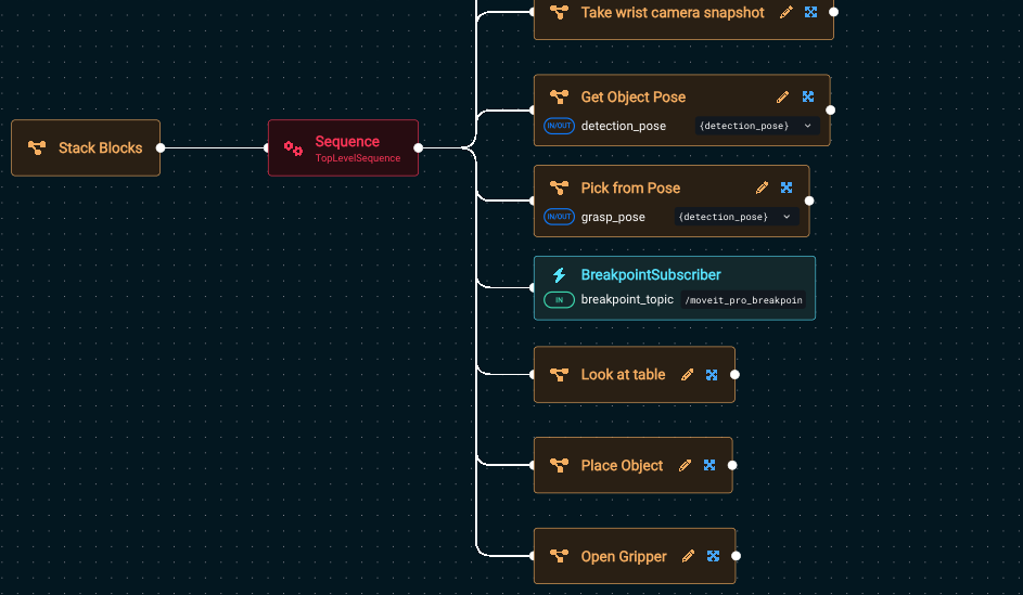
The Stack Blocks Objective should now look like this:
Notice the In/Out port icon next to detection_pose. All ports that are remapped into a subtree are always both in and out ports, because they are shared memory pointers between the parent Objective's and the subtree's blackboard.
Overview of the Task Constructor
In the previous step you added the Pick from Pose subtree. In this section we want to briefly mention that under the hood, it is using the MoveIt Task Constructor (MTC).
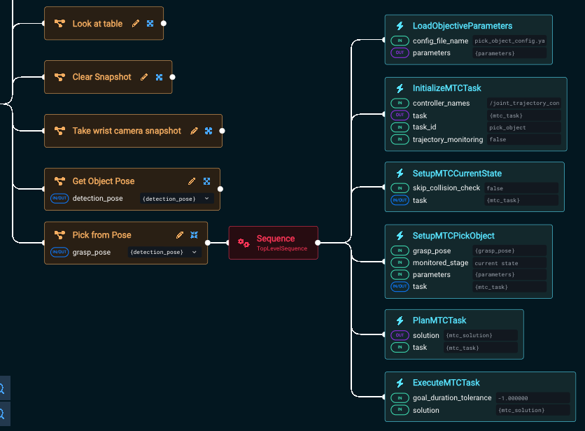
Click on the expand X button on the Pick from Pose subtree to see what's inside. The contents should look like this:
What is MoveIt Task Constructor (MTC)?
MTC enables you to break down complex planning tasks into multiple interdependent steps for use by motion planners. For example, to pick an object a robot must plan for multiple dependent goals in an exact order:
- Open the gripper
- Move to a pre-grasp position
- Approach the object
- Close the gripper
- Lift the object
MTC is used to plan a solution to the multi-task problem, given an object’s pose, and execute the plan.
Benefits of MoveIt Pro MTC Behaviors
MoveIt Pro provides a library of Behaviors to make using MTC easier. They provide a simplified way to create, plan, and execute MTC tasks. You can:
- Use Behaviors to set up and extend the task with common building blocks
- Choose from a variety of building blocks
- Reuse components of existing tasks much easier than writing low-level C++
Relevant MTC Behaviors
There are many built-in MTC Behaviors, you will use these to build your picking Objective:
InitializeMTCTaskcreates a task object and initializes the common global properties like trajectory execution info. The task object is then stored on the blackboard to be modified by following Behaviors.SetupMTCCurrentStatetakes the created task and sets up a generator stage corresponding to the current state as the task's start state.SetupMTCPickObjectis our custom Behavior which adds the stages required to describe the pick-planning problem to the task.PlanMTCTaskcalls the plan() function of the given MTC task and stores the solution to the blackboard.ExecuteMTCTaskreads an MTC solution from the blackboard and executes it.
The SetupMTCPickObject Behavior will be removed in 8.0 and replaced with a subtree.
Overall MTC is a complex topic that we do not cover in these getting started tutorials.
Place the object
Finally, let's put the finishing touches on our Stack Blocks Objective by adding these existing, pre-built subtrees:
- Add
Look at Table - Add
Place Object - Add
Open Gripper
Place Object is an example subtree that will put something in the robot's end effector at a pre-defined waypoint. Adding the Look at Table subtree before placing the object is needed so that the planner will approach the placement point from above.
Your fully finished Stack Blocks Objective should look like this:
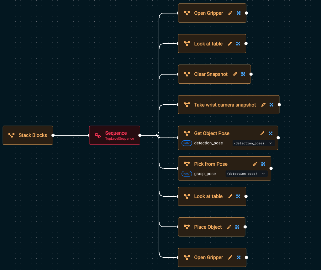
Run the Objective and you should see the robot pick up a block, move to the Look at Table waypoint, then plan a placement trajectory and ask for approval:
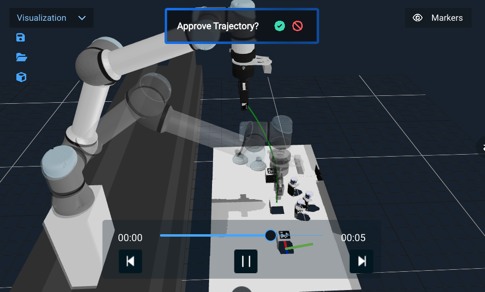
User Approval
The approval step is optional but can be nice for visualizing what the robot is about to do. MoveIt Pro provides various built-in Behaviors for user interaction for applications that require human in the loop. In our example, your Place Object subtree includes this capability by using the Wait for Trajectory Approval if User Available subtree, which checks if there is a UI attached, and if so asks the user to approve the trajectory.
Once you approve the trajectory, the robot should stack the block ontop of the other:
You won’t see the blocks being stacked in the “Visualization” pane, it is only shown in the simulated camera feeds, for example under /scene_camera/color and /wrist_camera/color.
Now let's learn how to debug planning failures.
Add a Breakpoint
To debug what is occurring in an Objective, insert a breakpoint using a BreakpointSubscriber.

Edit your Stack Blocks Objective, and add a BreakpointSubscriber in the middle, right after Pick from pose
Run the Objective, and you should see the robot pick the cube, then the Objective will wait at the breakpoint until the Resume button in the top right corner is pressed.
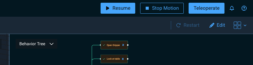
At this point, you can move the Visualization pane to get a better look at the scene, dig into the Blackboard parameter values such as the current value of detection_pose, or other debugging needs.
Press Resume to finish running the Objective.
Resetting & Manipulating the Simulation
In previous sections the robot was moving blocks around on the table. If your blocks get into a state you don’t want them, you may desire to reset the simulaton. There are two options for this:
- You can restart MoveIt Pro from the command line, or
- Run the MuJoCo Interactive Viewer to reset the simulation.
Performance Note: Running the MuJoCo Interactive Viewer alongside MoveIt Pro can impact system performance, and may not be feasible for lower-powered systems.
To enable the MuJoCo Interactive Viewer:
-
Exit MoveIt Pro using CTRL-C at the command line
-
Navigate at the command line to a specific folder within the
lab_simrobot config:cd ~/moveit_pro/moveit_pro_example_ws/src/lab_sim/description/ -
Open
picknik_ur.xacrousing your favorite editor / IDE. We recommend VS Code. -
Search within the XML file for the
ros2_controltag -
Find the line that says
mujoco_viewerand flip the boolean totrue.<param name="mujoco_viewer">true</param>
Re-launch MoveIt Pro and the MuJoCo Interactive Viewer should launch alongside MoveIt Pro.
Within the viewer, you can move objects around manually with a "hand of god"-like functionality:
- Double-click the object you want to move
- To lift and move: CTRL+Right Mouse
- To drag horizontally: CTRL+SHIFT+Right Mouse
You can reset the simulation using the Reset button on the bottom left menu under the section "Simulation".

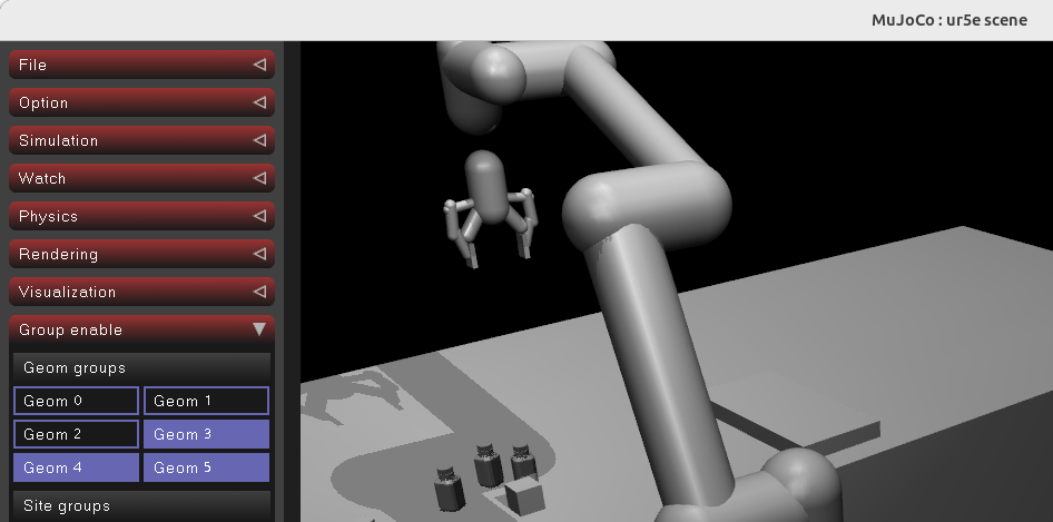
Finally, you can see useful debug information about the collision bodies by switching the "Geom Groups" under the section "Group enable":
- Toggle off Geom 0-2
- Toggle on Geom 3-5
Learn more about configuring the simulator at the MuJoCo configuration guide
Point Cloud Registration with Iterative Closest Point (ICP)
There are many other perception capabilities within MoveIt Pro beyond AprilTags, and in this section, we’ll learn about point cloud registration.
Point cloud registration is the process of localizing an object within a point cloud, given a CAD mesh file as an input. This is used in robotics for locating a part within a workspace, as an input to manipulation flows like polishing and grinding parts.
Typically, point cloud registration starts with an initial guess pose, which might be from an ML perception model, or based on where an object should be by the design of the robot workspace. This initial guess pose should be close to the object being registered, but does not have to be exact. The registration process then will find the exact pose using one of several algorithms, such as Iterative Closest Point (ICP).
Iterative Closest Point (ICP) is a foundational algorithm in robotics used to align 3D point clouds by estimating the best-fit rigid transformation between two sets of data. In robotic applications, ICP plays a critical role in tasks like localization, mapping, object tracking, and sensor fusion by helping a robot match its current sensor data to a known map or model. The algorithm works by iteratively refining the alignment based on minimizing the distance between corresponding points. While powerful, ICP requires a reasonable initial guess to avoid converging to an incorrect local minimum and is most effective when there is significant overlap between point clouds.
In Moveit Pro, the RegisterPointClouds Behavior provides this capabilitiy:

We'll explore an example application:
Edit the Register CAD Part Objective so that we can skim its architecture:
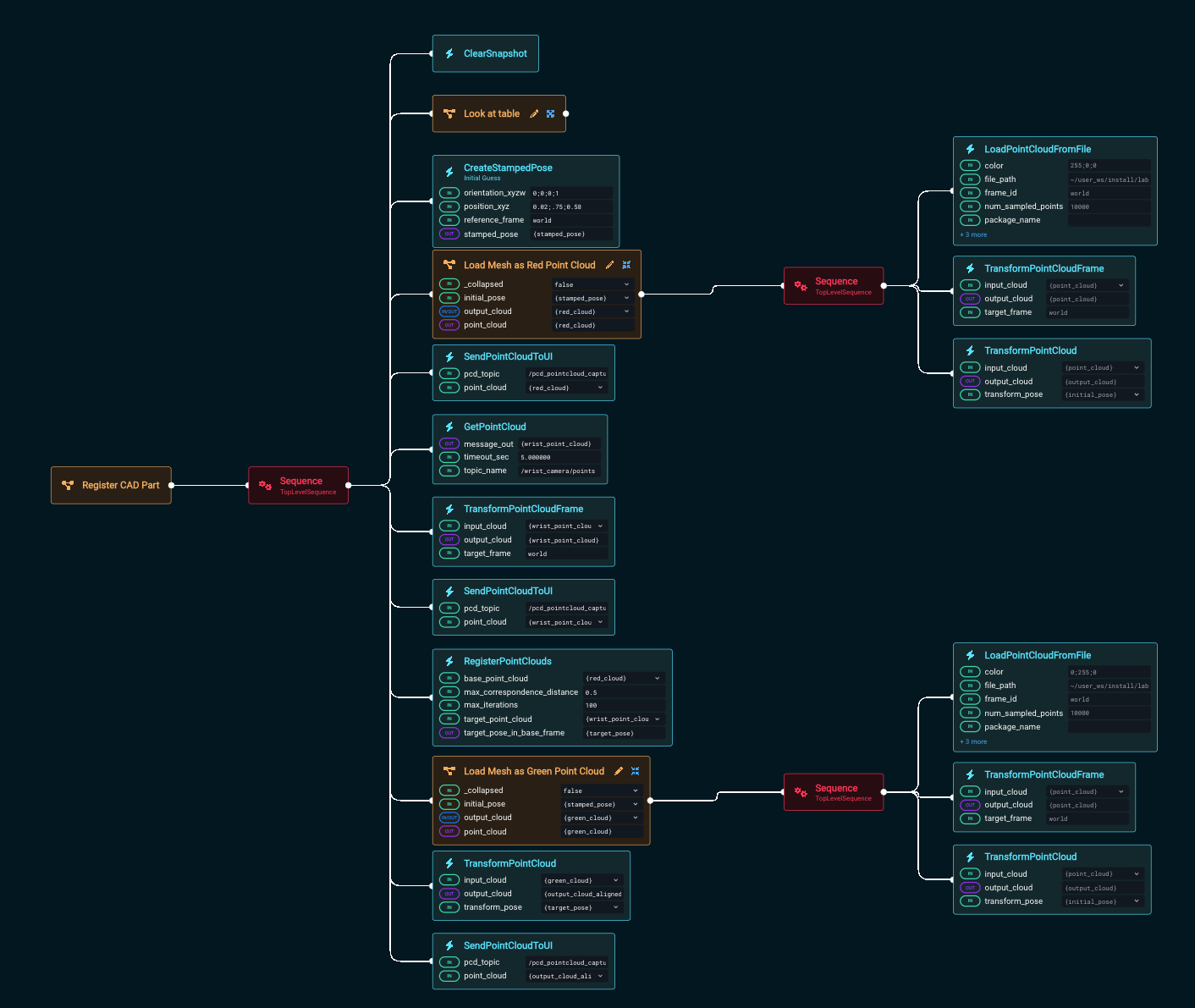
You’ll see the following overall flow:
- Move the camera on the end effector to look at the area of interest and take a point cloud reading, visualized in green
- Create an initial guess pose
- Load a mesh of a cube as the guess pose and visualize it in red
- Register using ICP the initial guess point cloud to the actual camera point cloud
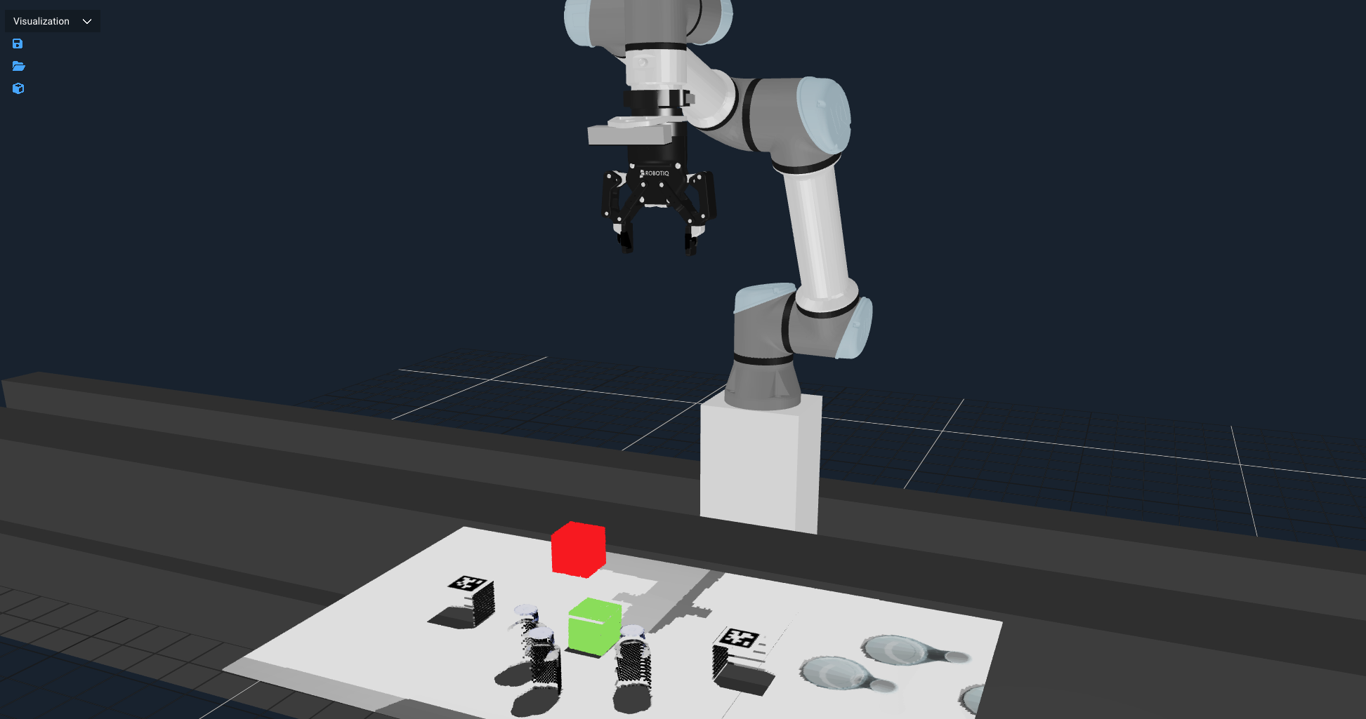
Next, Run the Objective, and you should see two point clouds appear, first a red one above the table (the initial guess), then a green one that matches the closest cube to the initial guess.
Next we will modify the guess pose.
- Edit the Objective
- Change the x, y, and z values in the
CreateStampedPoseBehavior to(0.2, 0.75, 0.6). - Run the Objective again and notice how the new guess will register a different cube.
Advanced: As an additional hands-on exercise, you can replace the Get Object Pose subtree in the Stack Blocks Objective with this Register CAD Part Objective.
Point Cloud Segmentation using ML
Point Cloud Segmentation with Machine Learning (ML) refers to the process of automatically dividing a 3D point cloud into meaningful regions or object parts based on learned patterns. Instead of relying solely on hand-tuned geometric rules (like plane fitting or clustering), ML-based segmentation trains models to recognize complex structures and variations directly from data. These models can classify points individually (semantic segmentation) or group them into distinct object instances (instance segmentation).
In this section we will explore the example Segment Point Cloud from Clicked Point Objective that demonstrates using ML for perception. It uses the GetMasks2DFromPointQuery Behavior which calls the ML model Segment Anything Model (SAM2) to find objects of interest.
The Objective:
-
Prompts the user to click on three objects in the color wrist camera image. The number three is arbitrary, it can be one or more.
-
Creates a 2D mask of the object using SAM2
infoMask: A 2D binary image where each pixel indicates whether it belongs to the segmented object (foreground) or the background, typically generated by models like SAM for isolating objects.
-
Converts the 2D mask to a 3D mask, mapping the mask into the 3D point cloud
-
Applies the 3D mask to the point cloud, removing everything except the chosen object(s)
Run this yourself:
-
Run the
Segment Point Cloud from Clicked PointObjective. -
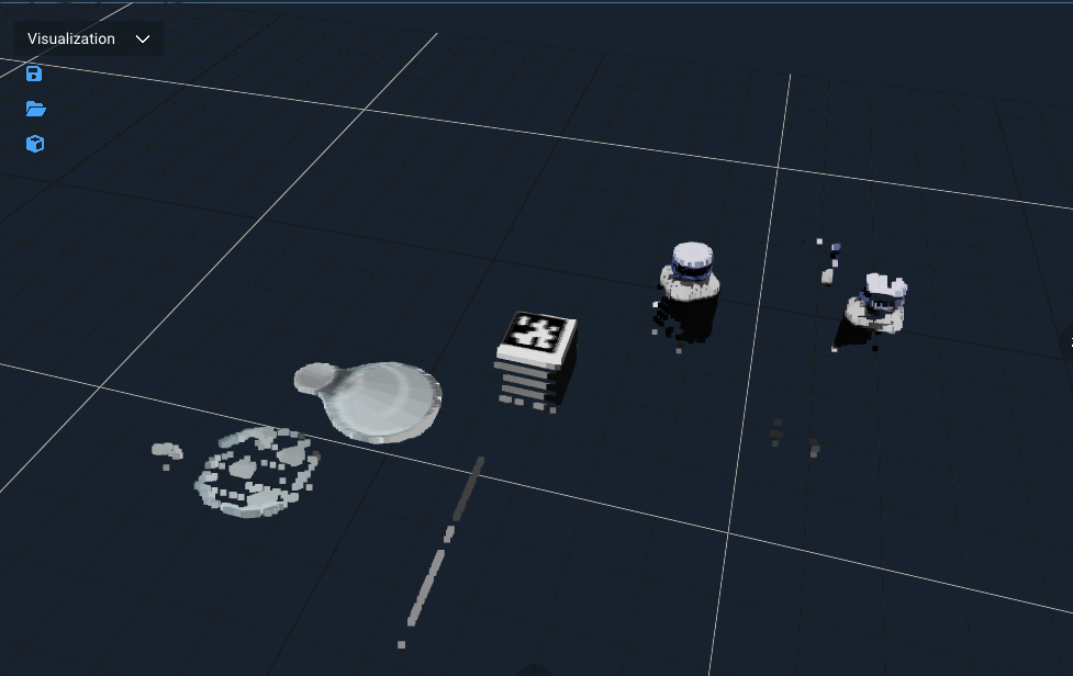
Ensure the view port
/wrist_camera/coloris visible -
It should prompt you to Click on three objects of interest
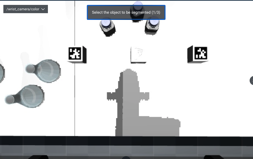
-
It should then segment out the point cloud for those objects and visualize them. Note that in this screenshot it did not find exactly three objects, due to unpredictability of modern ML models.
Advanced: For another hands-on exercise, you can use GetGraspableObjectsFromMasks3D to convert the 3D mask to a graspable object, then ExtractGraspableObjectPose to get a pose that can be used with your existing Pick from Pose subtree.
Task Constructor Debugger
Earlier we briefly touched on the Task Constructor; in this section we will explore more how to debug with the MTC debugger view.
We first need to trigger a MTC failer - to do this we will use teleoperation.
Click on the Teleoperation button at the top right, select the Interactive Marker mode, and move the virtual marker arrows so that the robot end effector will collide with its own linear rail base, similar to shown in the picture:
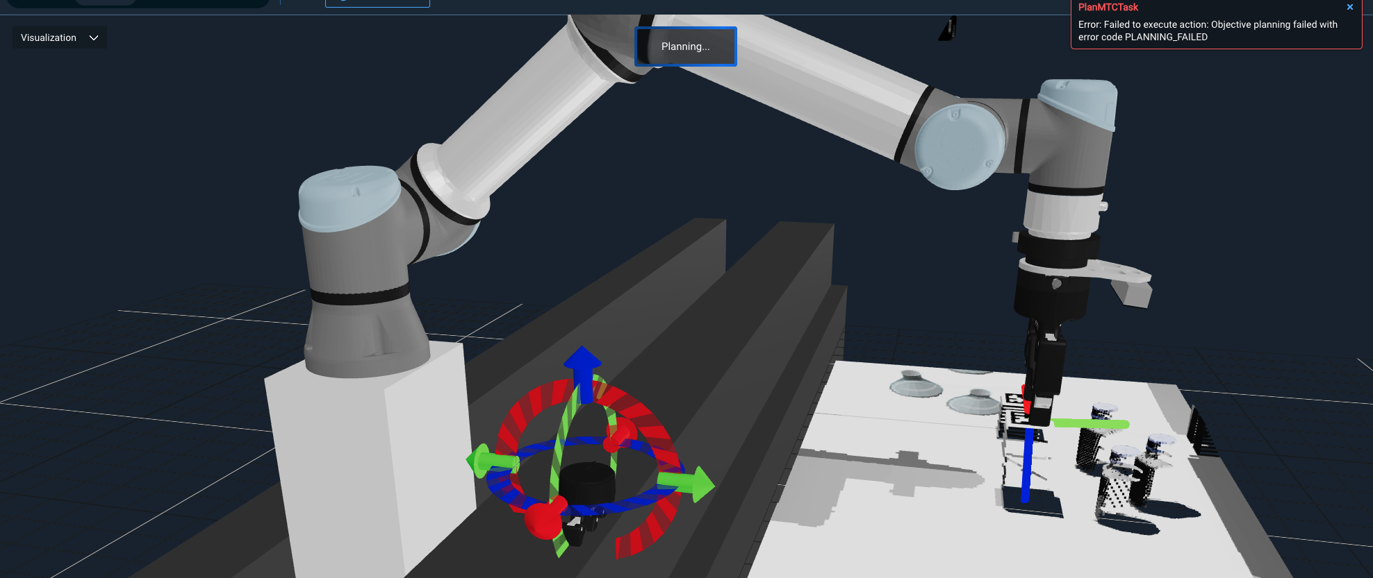
You should see a popup message that PlanMTCTask has failed with error code "PLANNING_FAILED".
To debug this further:
-
Switch to the Behavior Tree view port, if not already visible
-
Expand the
Request TeleoperationBehavior Tree: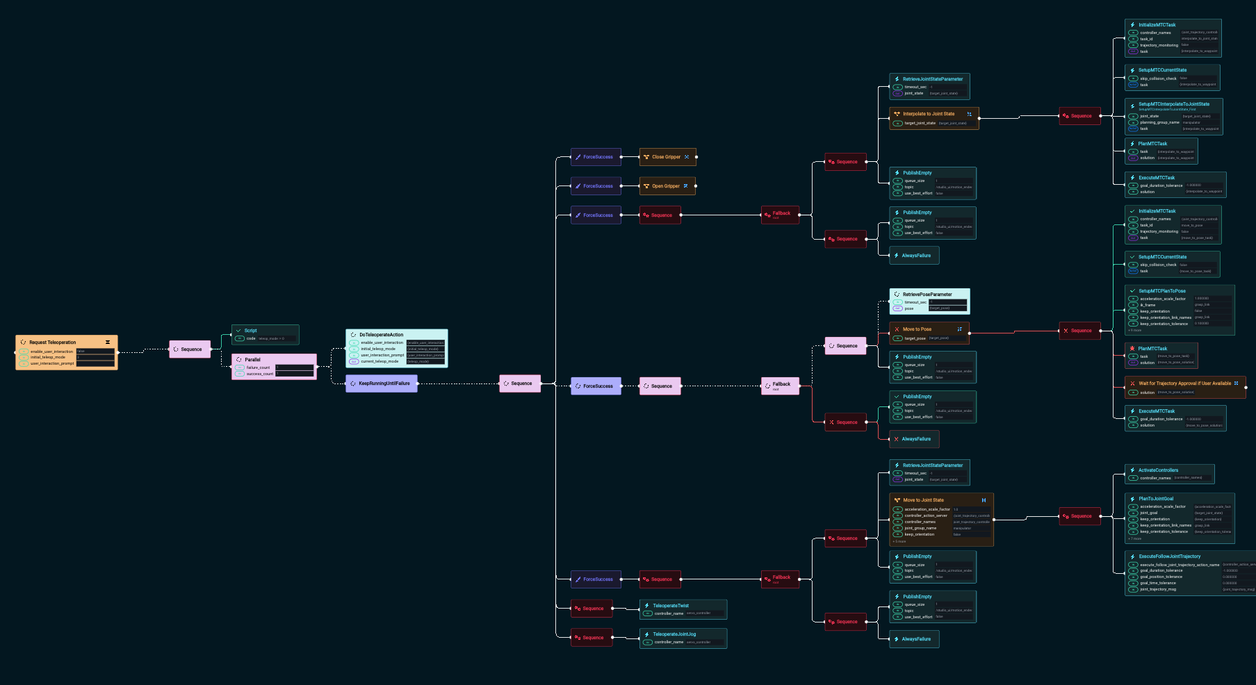
-
Find the failing node, which should be named
PlanMTCTaskand highlighted in red: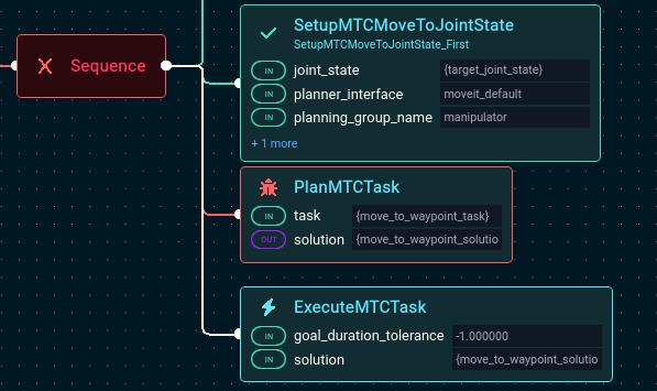
-
Click on the bug symbol to open the MTC Debugger:

-
You should see this view that allows you to better understand what failed:
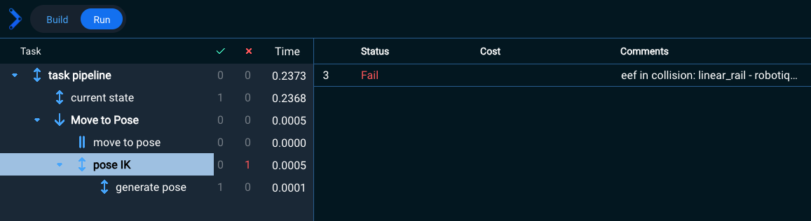
-
Highlight the row on the left labeled
poseIK- this is the failing MTC stage. -
You should see a comment that explains why it failed. In this case, it says “eef in collision” which means the robot’s end effector is in collision with the linear rail.
-
Choose Return to Objective in the top right corner to close the MTC Debugger view.
Summary
By completing this tutorial, you've gained hands-on experience with powerful tools in MoveIt Pro for perception-driven manipulation. You've learned how to integrate fiducial detection, point cloud processing, and modular Behavior Trees to create reusable, intelligent robotic Objectives. You also explored debugging techniques and simulation reset tools that support more robust development workflows.
🎉 Congratulations, we're now ready to move to the next tutorial!