3. Mobile Manipulation & Cartesian Planning
🕒 Duration: 1-2 hours
Tutorial Overview
This tutorial introduces the powerful mobile manipulation capabilities of MoveIt Pro, combining navigation, perception, and whole-body planning into a unified workflow. Set in the hangar_sim environment, you’ll learn how to navigate using ROS Nav2, perform ML-based pick-and-place tasks, execute precise Cartesian trajectories, and generate automated coverage paths. Whether you're planning point-to-point movements or scanning surfaces in a warehouse, this tutorial gives you hands-on experience with advanced robot Behaviors that blend mobility, manipulation, and perception.
Pre-reqs
You should have already installed MoveIt Pro. We will assume you have already completed Tutorial 2 and know how to build Behavior trees.
Start MoveIt Pro
Launch the application using:
moveit_pro run -c hangar_sim
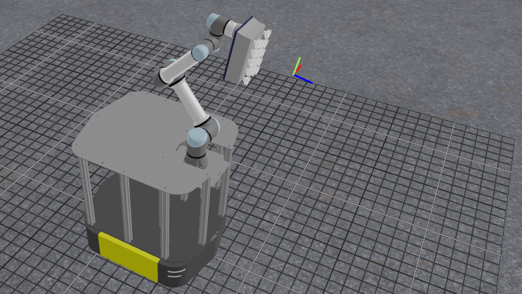
The hangar_sim robot config launches a virtual environment representing an airplane hangar with a mobile manipulator. The robot has a mobile base, a robotic arm, and integrated sensors.
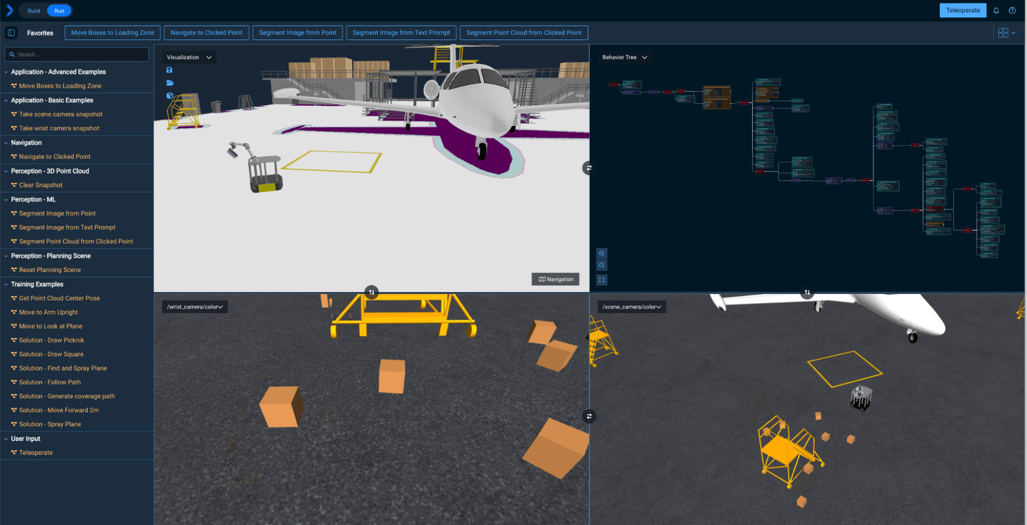
Mobile Base Navigation with Nav2
In this section, we explore basic navigation of the mobile robot using ROS’s Nav2 stack. Nav2 provides autonomous navigation capabilities using maps and localization.
Navigate to a Location in the Hangar
-
Start the Objective
Navigate to Clicked Point. -
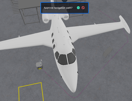
In the Visualization pane, click anywhere in the hangar to set a navigation goal.
-
Approve the green check mark to start movement.
-
Repeat this process to then move the robot back to the yellow box zone for our next exercises.
Occupancy Grid
MoveIt Pro is able to visualize the occupancy grid, global costmap, and local costmap that is published by Nav2 in the UI. The occupancy grid is the map that Nav2 uses to internally represent a top down view of the environment that the robot is navigating in. The occupancy grid is typically generated with some type of mapping or SLAM tool offline. The grid cells in the occupancy grid encode information if that cell is free, occupied, or unknown.
Use the Navigation toggle button (bottom-right of Visualization pane) to show and hide the Occupancy Grid, to get a better understanding of what that is.

Global Costmap
The global costmap is an internal representation of the environment where now there are costs associated with each grid cell. These costs typically reflect safety margins around obstacles (known as the “inflation layer”) as well as additional pertinent information. The global costmap is used by a global planner to generate an end-to-end path from the robot’s current position to a goal.
Use the Navigation toggle button (bottom-right of Visualization pane) to show and hide the Global Costmap, to get a better understanding of what that is.
Local Costmap
The local costmap provides a small representation of the environment that is immediately around the robot. Like the global costmap, the local costmap has costs associated with each grid cell. The local costmap is intended to capture dynamic changes in the environment at a much higher frequency. The local costmap is used by the local controller to generate velocity commands for the robot base so that it can follow the end-to-end path generated by the global planner while still avoiding obstacles near the robot. To learn more, see Nav2’s Environmental Representation page.
Use the Navigation toggle button (bottom-right of Visualization pane) to show and hide the Local Costmap, to get a better understanding of what that is.
The parameters for the local and global costmaps are defined under the global_costmap and local_costmap namespace in the filesystem under ~/moveit_pro/moveit_pro_example_ws/src/hangar_sim/params/nav2_params.yaml. Try adjusting the inflation_radius parameter in the file and re-launching MoveIt Pro to see the effect on both costmaps.
Planners and Controllers
There are some navigation Behaviors in MoveIt Pro which require providing the name of a planner or controller as an input. In Nav2, the planner is used to compute a path to complete some Objective function. Generally this means to compute a path to a goal. The planner uses the global costmap to generate the path. Nav2 provides a number of planners, such as: NavFn Planner, SmacPlannerHybrid, SmacPlanner2D, SmacPlannerLattice, and ThetaStarPlanner.
In Nav2, a controller is used to generate the command velocity for the robot so that it can follow a global path. The controller uses the local costmap to generate the path such that it avoids high cost areas in the local costmap while still trying its best to follow the path. Nav2 provides a number of controllers, such as: DWB Controller, TEB Controller, Regulated Pure Pursuit, MPPI Controller, Rotation Shim Controller, Graceful Controller, and Vector Pursuit Controller.
Whole body control with Teleoperation
Beyond mobile base-only navigation, MoveIt Pro can combine arm and wheel planning using whole body planning. This approach does not use Nav2 under the hood. Manually try it out for yourself:
-
Enter Teleoperation mode from the toolbar.
-
In Waypoint Mode move to waypoint
View Boxes. -
Switch to Pose Jog mode and use sliders or arrows to move the end effector.
If stuck in collision, switch to Joint Jog, disable collisions, and move out.
ML-Based Pick and Place
Next we will explore an example Objective that involves using machine learning to detect scattered boxes, and leverage our mobile robot to move the boxes to a predefined zone in a warehouse.
Move Boxes to Loading Zone
The robot uses ML vision models to find box locations and MoveIt Pro’s planners to autonomously move them.
This Objective requires a fairly powerful computer to run, due to its use of several ML models. It is ongoing work to improve performance of these ML models, but you may not be able to run this example without NVIDIA hardware. If you can’t run this successfully that’s ok - skip it and know that the rest of this tutorial does not have the same system requirements.
Run the Objective Move Boxes to Loading Zone. Watch the robot scan a region, detect boxes, and place them in a zone.
The Objective is designed to operate in an unstructured environment. It relies on wrist camera images to extract scene information and generate a motion plan. First, the robot navigates to the general region where boxes are expected to be. Then, the wrist camera images are fed through a vision language model to extract segmentation masks for all visible boxes. The exact prompt used for segmentation can be tuned for better performance. Given the masks, motion planning is initiated for each possible box to be grasped. Once the first viable motion and grasp is found, the robot will navigate to that box and pick it up. After picking up the box, the robot will motion plan to the designated loading zone and drop the box off.
The performance of the Objective can be further increased by using different viewpoints for the wrist camera when finding box mask segments. The placing portion of the Objective can also be enhanced by accounting for the rotation of the box in the robot's gripper. That transform can be calculated using the registration result from ICP.
Panning around the Visualization UI can be tricky - on your mouse, try holding down the middle key and the right button at the same time to pan around and change your frame for zooming.
Cartesian Path Planning
In this section we will learn more about Cartesian path planning with our mobile manipulator. Cartesian planning is different than our previous tutorials, where we learned about free space planning. Cartesian planning creates a path where the robot’s end effector follows a precise series of poses in space, often along a straight line or curve. This is useful for painting, welding, spraying, drawing, or scanning—where the tool must stay in contact with or aligned relative to a surface.
Common characteristics of freespace planning:
- Path is defined in Cartesian (X, Y, Z + orientation) space.
- Planner ensures smooth transitions using waypoints.
- A drawback is that it is sensitive to collisions and IK feasibility.
This is in contrast to freespace planning, which plans a trajectory from a start to goal configuration without specific constraints on the path itself. Freespace planning solves for a valid, collision-free path in joint space, but it may produce curved, non-intuitive motions.
MoveIt Pro supports both approaches and allows blending them using composite Behaviors, depending on your task’s complexity.
A Pose in MoveIt Pro is represented by the PoseStamped type. These types contain the pose of a ‘child’ frame in the ‘parent’ coordinates.
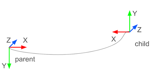
Cartesian plan to a single pose
Let’s start learning about Cartesian planning by planning to a single point. Later we will plan through a series of points.
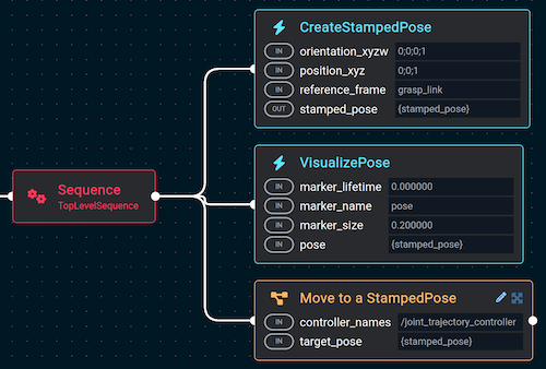
Let’s create a simple application that moves the robot forward 2 meters. Create a new Objective called Move Forward 2m that consists of three Behaviors:
- Behavior:
CreateStampedPose- orientation_xyzw =
0;0;0;1 - positions_xyz =
0;0;1 - reference_frame =
grasp_link
- orientation_xyzw =
- Behavior:
VisualizePose - Subtree:
Move to a StampedPose
Your Behavior tree should look like this:
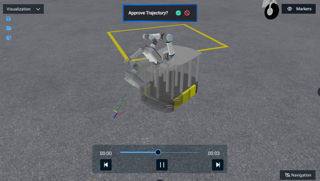
Run this new Objective and you should be prompted with the new trajectory. Approve it and watch the mobile manipulator move forward.
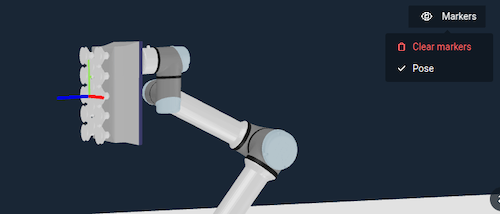
You can clear markers between steps to make visualizing things easier.
This pattern of creating a pose, visualizing it, and moving towards it is a common pattern in debugging robot Behaviors in MoveIt Pro.
Cartesian plan to multiple points
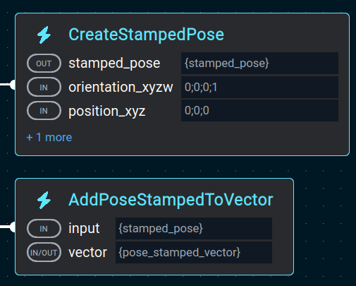
In the previous section we planned a straight line to a single point. Here we will Cartesian plan through multiple points, using a path. A path is a vector of stamped poses:
In our Behavior trees in MoveIt Pro, we typically create the pose and then add it to a vector of poses.
MoveIt Pro’s Cartesian planner is called PlanCartesianPath Behavior. We used this Behavior in the last section also, but it was hidden inside the Move to a StampedPose subtree.

It has many parameters that can be tuned - we’ll explain some here. First the blending radius - it smooths out the motion between straight lines:
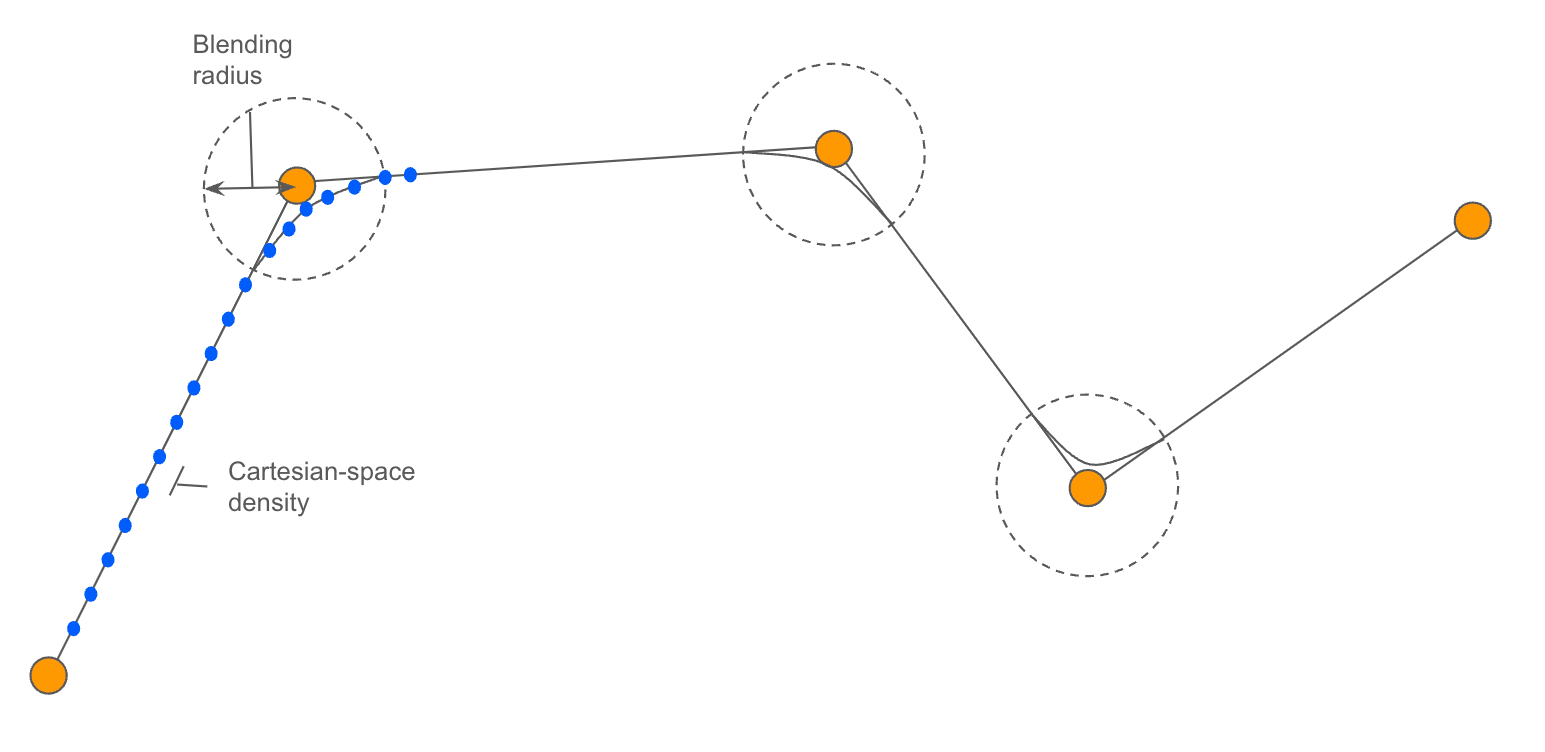
The Cartesian-space density is the distance between waypoints in motion plan.
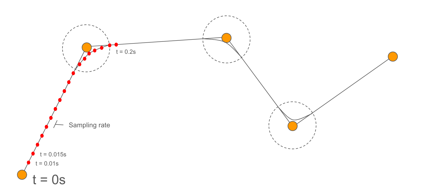
The trajectory sampling rate is the loop rate of the trajectory controller.
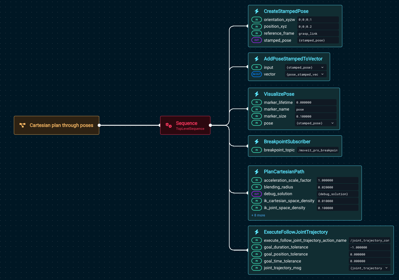
Create a new Objective called Cartesian plan through poses.
Next add the following Behaviors:
- Behavior:
CreateStampedPose- orientation_xyzw =
0;0;0;1 - positions_xyz =
0;0;0.2 - reference_frame =
grasp_link
- orientation_xyzw =
- Behavior:
AddPoseStampedToVector- input =
{stamped_pose}
- input =
- Behavior:
VisualizePose - Behavior:
BreakpointSubscriber - Behavior:
PlanCartesianPath - Behavior:
ExecuteFollowJointTrajectory
Your Behavior tree should look like this:
Before running, we recommend you get the robot in a good position by running the Objective Move to Arm Upright, which is a shortcut to move to a waypoint.
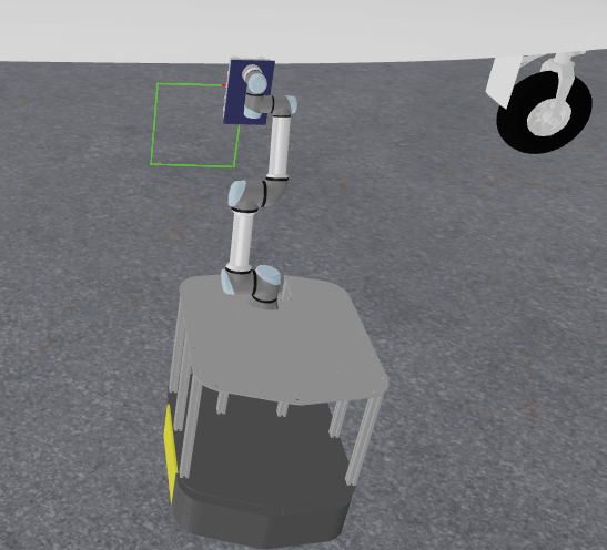
Now run Cartesian plan through poses and you should see it pause with the visualized pose:
Press the Resume button at the top right to continue its operation.
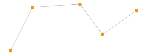
Cartesian plan with more points: drawing a square
To see a more complex Cartesian example, without having to build it yourself tediously, let’s draw a square.
- First, run
Move to Look at Plane - Then run
Cartesian Plan Simple Square
The robot should produce this result:
The key difference between this example and the previous is that the Cartesian planner is constraining both the end effector position and orientation, by setting the parameter position_only: false.

Feel free to explore the Behavior tree to better understand how this was accomplished.
Drawing Multi-Pose Paths
You can load more complex geometries from file, rather than having to hard code everything with Behavior tree nodes. In this section we load a path from a file called picknik.yaml.

We also use the ROS transform library TF to publish a static TF using PublishStaticFrame in the local frame. The full Behavior tree looks like this:
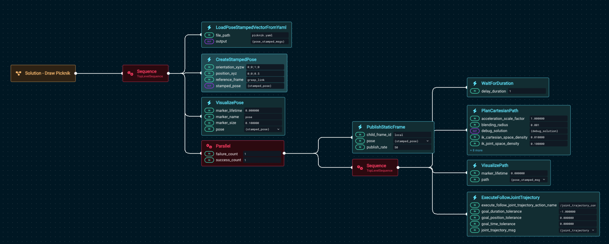
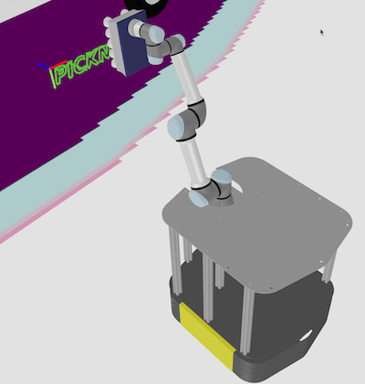
Run the example Objective Cartesian Draw Geometry From File and you should see:
ExecuteFollowJointTrajectory will trigger an error if the /joint_trajectory_controller is not active. If you see this error, add an ActivateControllers Behavior at the beginning of the Objective, to make sure the /joint_trajectory_controller is active. This will be fixed in release v7.7.
Coverage Path Planning
Coverage paths are used in a variety of applications including painting, spraying, sanding, smoothing, or inspecting an area. In this section we will explore how to auto-generate coverage paths for a simple rectangle. More complex coverage paths over contoured surfaces are also possible, of course.
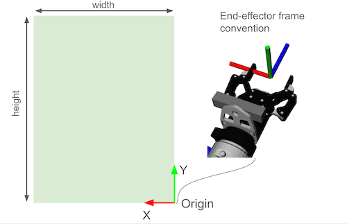
Coverage Path Conventions
You can specify the area to cover by providing:
- An origin (the bottom-right corner).
- The width
- The height
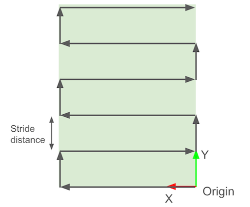
The following diagram explains this convention:
A lawn-mower path is automatically generated, with a given distance between strides.
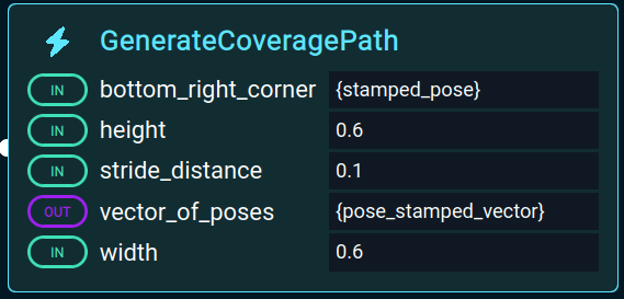
In MoveIt Pro there is a Behavior called GenerateCoveragePaths used to create these paths:
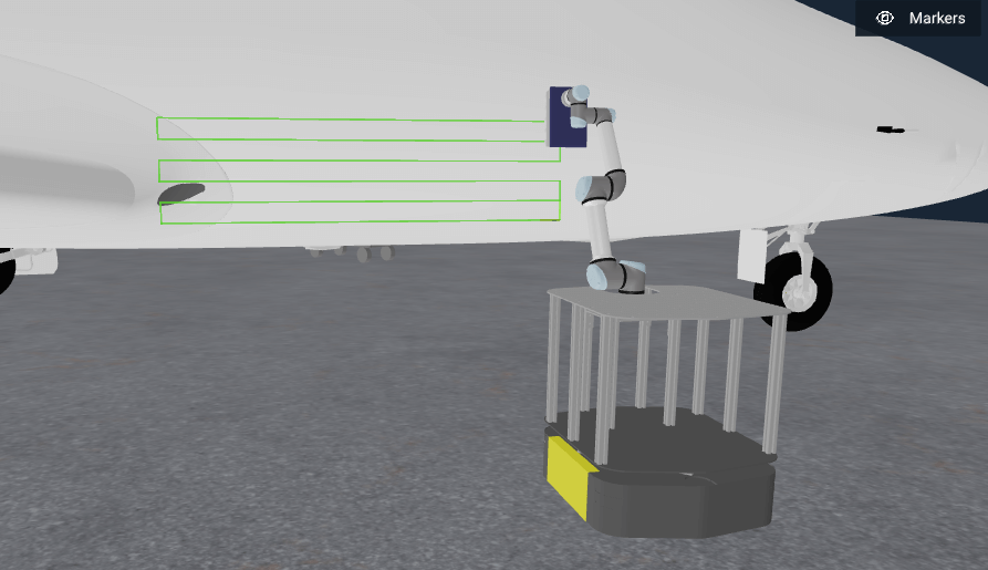
Run the existing Objective for this called Generate Grid Pattern on Airplane. You should see it do this:
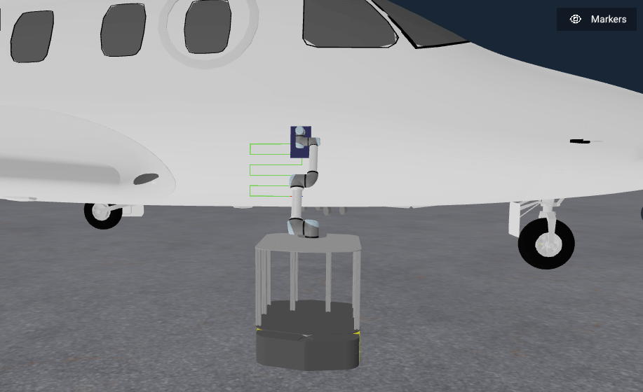
Seems like a small path, right? Let’s modify this Objective by editing the Behavior tree.
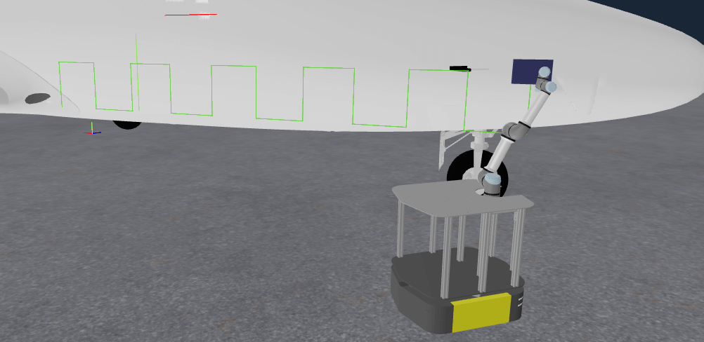
Find the Behavior called GenerateCoveragePath and open up the parameters sidepanel. Change the width to 2.0. You should now see a much more impressive path:
Feel free to adjust any other settings you would like, also.
Scan & Plan Workflow
In this final section we bring together all the pieces by combining perception with the Cartesian planning we’ve covered above. In this example the robot scans the side of the airplane before generating the motion plan.
Run the Objective Find and Spray Plane to see it in action. You should see:
Why so far away from the plane surface? In the examples in this hangar_sim world we have added a large amount of collision padding around the plane to prevent the robot from getting stuck under it during mobile base navigation. Unfortunately this has also prevented us from touching the surface during our manipulation tasks. Future work is to improve the simulation environment and examples to support both scenarios.
The key difference in this example is we use a pre-built subtree called Get Point Cloud Center Pose that returns the pose of the plane of the airplane sidebody:
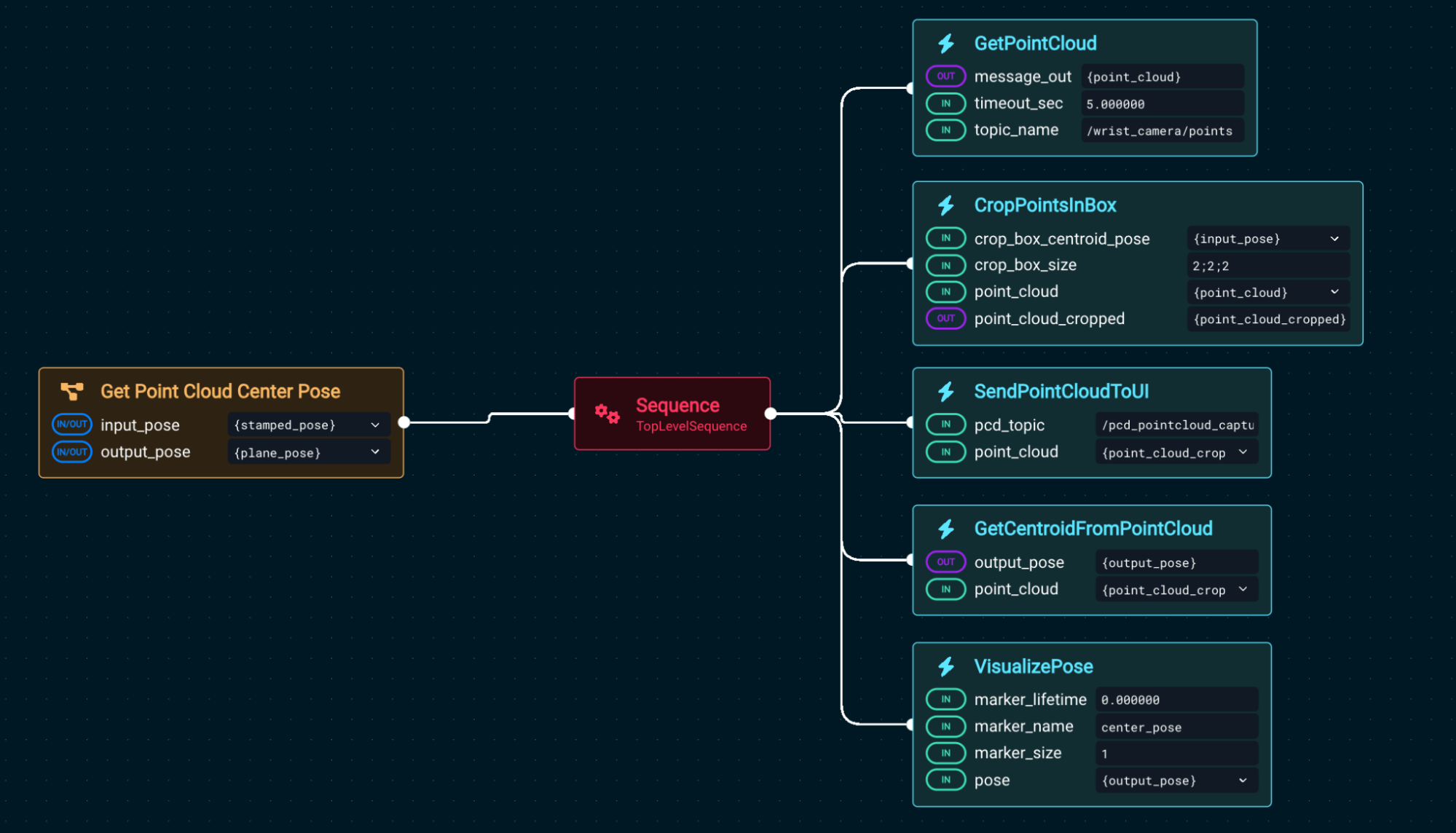
Using that center point, we generate the Cartesian plan. Let’s modify Find and Spray Plane to have a more dense scanning pattern. Edit the Objective and again find the Behavior GenerateCoveragePath. Open the parameter sidepanel and change the parameter stride_distance to 0.1.
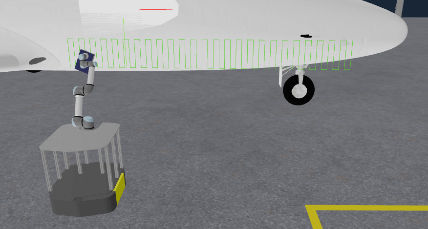
Run the Objective and you might notice the motion planner takes longer to compute the new path. You should then see the following path generated:
Summary
In this tutorial, you've tackled mobile base navigation, integrated machine learning for perception-driven pick and place, and explored the full power of Cartesian and coverage path planning. You've also seen how to combine scanning and motion planning in real-world workflows using MoveIt Pro’s Behavior tree interface. These techniques provide the foundation for building sophisticated autonomous systems that operate in dynamic, unstructured environments.
🎉 Congratulations, we're now ready to move to the next tutorial!